Mode
Following modes are available:
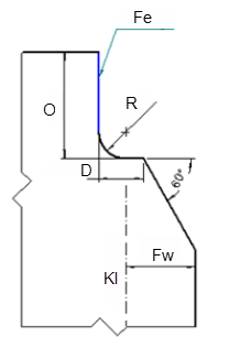
In the following images, Fe and Fw refer to free edge and flange width respectively. O refers to offset, R refers to radius, D refers to distance and Kl refers to the knuckle length.| Centered | Tangent |
|---|
 |  |
With the change in the mode, the bitmap image changes. If you double-click the bitmap image, it opens in a new window.
End Cut
In the End Cut area, you can define the end cut parameters. You can set the same end cut parameters for start and end extremities, by keeping the default chain mode.
When the chain mode is active, the parameter boxes for the End Extremity are dimmed. The Start Extremity parameters are applied to End Extremity.
To set different end cut parameters for start and end extremities, activate the independent mode. You need to click  . The icon changes to
  and the end extremity parameter boxes are available.