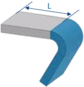
Creating a Flange | |||||
|
| ||||
-
From the
Detail section of the
action bar,
click
Flange
 .
The Flange dialog box appears.
 -
In the
Plate box, select a plate
or a panel
on which the flange is to be defined.
Important: When you select a panel, the split plate of the panel is selected. The edges on which a flange can be created are highlighted. -
In the
Edge box, select one or more highlighted
edges.
Tip: You can also extract edges using the Create Extract contextual command and select them. Important: The edge must be straight, and must belong to the boundary element of the plate. - In the Mode list, select Centered or Tangent.
-
In the
Flange Width box, enter a value (say
300mm).
You can use one of the following options to select a reference for width calculation:
Option Reference 
Inner face 
Outer face -
In the
Angle box, enter the required bending angle
value (say
60 degree).
This value indicates the angle by which flange will bend from the plate or a panel .
Note: Click Flip to change the flange orientation. - In the Radius box, specify radius between the plate and the flange.
- Optional:
To create a flange without increasing the overall length of the plate, select
one of the following Trim options:
Without Trim Inner Trim 
Outer Trim 


Where, L is length of the plate. - Optional:
Under the
Limits area, select the start and end limits.
You can select reference planes or surfaces to limit the flange. You can also define the offset value for the start and end extremity.
- Optional:
Under the
End Cut area:
-
In the
Distance box, enter the distance from the
free edge, to position the end cut.
Important: The distance should not be greater than flange width. -
In the
Angle box, enter the required value.
The angle is always counted from the vertical edge of the flange.
- In the Radius box, enter the end cut radius.
You can set the same end cut parameters for start and end extremities, by keeping the chain mode active.
-
In the
Distance box, enter the distance from the
free edge, to position the end cut.
-
Click
OK.
The flange is created. In the tree, the flange is aggregated under the plate or split plate of the panel.
- Optional:
To edit the flange, select the flange in the
work area
and click
Flange
 on the
context toolbar.