Built-In Endcut Parameters | ||
| ||
About Built-In Endcuts
Built-in endcuts correspond to the algorithm that provides two volumes. While creating an endcut, it is considered that a profile section has at least four edges:
- MoldedFlange1
- MoldedFlange2
- Webinner+
- Webinner-
You can create an endcut table that lists the endcut name, type, name of the corresponding bitmap image, and applicable limit type. Then set it in the Structure Resource table of the Data Setup.
Recommended Parameters
The built-in endcut parameters are defined in the endcut reference.
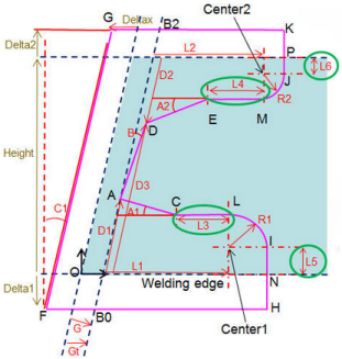
For the web element of the profile, following parameters are taken into
account:

- G
- Gap between the cutback plane and the end cut measured along the normal to the cutback plane.
- Gt
- Gap between the cutback plane and the end cut measured along the trace of the profile.
- C1
- Computed angle from the cutback plane.
The other length value parameters are L1, L2, R1, R2, D1, D2, D3, L3, L4, L5, and L6. The angle value parameters are A1, A2, and B.
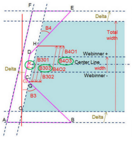
For the flange element of the profile, following
parameters are taken into account:

- Origin Point
- Gives the starting point for cutting the profile. The origin
point is computed as a mid-point of MoldedFlange1. If MoldedFlange1 is not
available, it is computed as a mid-point of Webinner+ and Webinner-.
The following parameters define the origin point:
- OriginPoint_X
- OriginPoint_Y
- OriginPoint_Z
You must add the Comp_ prefix to these parameters to compute their values automatically.
- B3O1
- Location of B3 as distance from face WebInner+.
- B3O2
- Location of B3 as distance from face WebInner-.
- B3O3
- Location of B3 as distance from the web center.
- B4O1
- Location of B4 as distance from face WebInner+.
- B4O2
- Location of B4 as distance from face WebInner-.
- B4O3
- Location of B4 as distance from the web center.
- K
- Gap between the CD line and GH line.
- C2
- Computed angle from the cutback plane.
The other angle value parameters are B1, B2, B3, and B4.
Additional Parameters
Apart from the above recommended parameters, you can also define additional parameters as per your requirement.
You need to manage the values of these parameters using an expert rule. For a sample expert rule, see 3DEXPERIENCE Native Apps Content Reference Guide: Samples for Action Rules.