Creating a Coordinate Annotation | |||
| |||

Notes:
- Double-click the annotation to edit it.
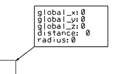
- When a generated object is selected, the graphic representations of placement nodes appears, and you can select a node to place the coordinate annotation.
- Depending on the type of selected object, the graphic representation shows fluidic nodes, axis system, or structural openings.
- Depending on the selected option, a node is extracted from the element and an annotation is computed and placed on it.
- In the case of geo-location computation, the geo-location needs to be applied before
selecting the element.
Geo-location, reference position, and distance to reference can be defined within the same template with provided parameters.