-
From the
Smart Annotation section of the
action bar,
click
Elevation Annotation
 .
.
-
In the Elevation Annotation Definition dialog box, click
Catalog Browser
 and select a
template.
You can also select another elevation annotation to reuse its
template.
The template chapter is saved as
preference for next time usage.
The template is selected and the
Annotation list displays the type.
The representation or
content of the annotation depends on the designed template and the parameters
defined in the template.
-
In the view, select an element.
You can select a generated item or an
interactive element such as a point or a line. When a generated object is
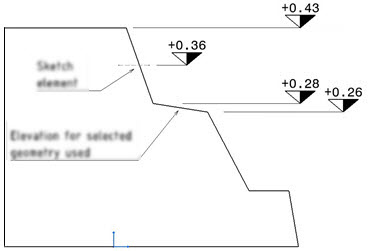
selected, you can indicate that elevation for selected geometry is used which
then computes elevation for only that particular edge of selected geometry.
For example, see the below image.
-
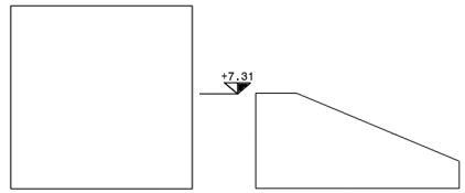
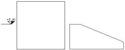
Under Position, select an
option from the following:
| Place on View Side
|
Place on Object Side
|
|
|
Note:
The object on the right side is selected for creating the annotation.
-
Under
Computation, select the
Elevation for selected geometry check box.
-
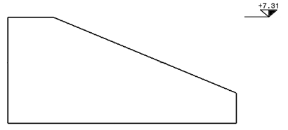
From the Mode list, select a
mode from the following:
| Top of Object
|
Bottom of Object
|
|
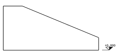
|
- Optional:
Under Reference Plane, select a reference option and
then select a plane.
- Select existing plane: You can select a default
reference plane (Z=0/X=0/Y=0) or any plane used by other elevation annotations
from the
Plane selection list.
- Select plane in 3D: You can select any plane from the 3D area or from the project plane system even
if the reference plane is not in the view.
The elevation annotation computes its value in reference to a plane. By default, the plane of
reference is the zero of the global axes if no input is provided and it depends
on the view plane definition. For example, if the view plane is parallel to the
XY/YZ/ZX plane, the default reference plane is (Z=0/X=0/Y=0) respectively.
- Optional:
In the Parameters tab, modify the required parameters.
- Optional:
In the
Action Management tab, route the annotation
action argument to a different feature.
For more information, see Routing Action Links.
Note:
If the elevation annotation is created for an interactive sketch
element, the elevation value is not recomputed when the position of the element
is changed in the view. It is updated only during a view update.


