About Parametric Panel | ||
| ||
In the Position list, select the appropriate option to define the location and orientation of the parametric panel.
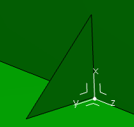
- 3D Axis
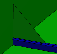
- Plate/Stiffener
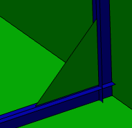
- Stiffener/Stiffener
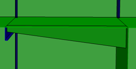
- Multi Limits
- 3D Axis
- 3D Axis
- Select an axis system in the work area.
You can create an axis system by right-clicking the box and select Create Axis System. You can select multiple axis system.
The H and V axes of the contour sketch are aligned with the X and Y axes of the axis system.

- Plate/Stiffener
- Plate
Select a plate in the work area.
Use the Flip button to toggle the orientation across the plate.
- Stiffener
Select a stiffener in the work area, it appears in the Stiffener box.
You can select more than one stiffener at a time.
Important: By default, the MoldedFlange2 face of the stiffener is selected. See Naming Section Edges. Click
 to check the list of the selected stiffeners. You can replace or remove the previously selected stiffener.
Use Flip to toggle the orientation across the stiffener.
- Support
- The Support box displays the element on which the stiffener is created. The parametric plate/standalone panel will be created on this support. You cannot edit or remove the support.
- Offset
In the Offset box, you can specify the offset by which the plate is offset from the support.
Use a negative offset value to reverse the offset direction.

- Stiffener/Stiffener
- Stiffener
Select stiffeners or plates in the work area. The selection appears in the Stiffener boxes.
You can select more than one stiffener at a time.
Important: By default, the MoldedFlange2 face of the stiffener is selected. Click
 to check a list of the selected stiffeners. You can replace or remove the previously selected stiffener.
Use Flip to toggle the orientation across the stiffener.
- Support
- The Support box displays the element on which stiffener is created. The parametric plate/standalone panel will be created on this support. You cannot edit or remove the support.
- Offset
In the Offset box, you can specify the offset by which the plate is offset from the support.
Use a negative offset value to reverse the offset direction.

- Multi Limits
- Support
-
Select either a plate or a surface from the work area to support a plate. The supporting element must be compatible with the
category selected. The selected element appears in the Support box.
You can also:
- Right-click the Support box, and choose Select Reference Plane to select a plane from predefined plane system.
- You can create a plane using Create Plane.
Click
 next to the Support box to display the elements list. From the displayed list, select the support. You can use the Remove and Replace commands to remove and replace the selected reference, respectively.
 - Offset
In the Offset box, you can specify the offset by which the plate is offset from the support.
Use a negative offset value to reverse the offset direction.
- Limits
- In the Limits area, select the elements to define a boundary for plate.
To select the elements:
- Select the planes in the work area.
- Right-click in the Object column in the Limits area, and choose Select Reference Plane.
You can select:
- Geometrical entity.
- Structural object (panel or stiffener).
When you select a stiffener, an appropriate face (MoldedFlange2 or WebInner) of the stiffener is automatically selected as a limiting element.
- A volume or a closed surface.
- Particular faces of flanges created on a plate. You need to press Ctrl or Alt during the selection. Pressing Ctrl highlights the faces near the pointer, whereas pressing Alt displays the list of nearby faces.
If you select a face of a flange as a limit and you want to select the associated panel or plate as another limit, you need to press Ctrl or Alt and select a face of the panel or plate.
- Particular faces of the stiffener (flange or web) as the limiting elements for the plate. Press the Alt key while selecting the stiffener. It displays the faces which can be selected as a limit. See Naming Section Edges.
Click Flip to change the orientation across selected limits. The Side column displays whether the orientation of limiting element is Normal or Invert.
Click Remove to cancel the previously selected limits. During the edition mode, the Remove button is unavailable.

Important: The Multi Limits mode provides a proper order of limits. For example, if the limit L2 is changed, the order of the other limits is unaffected. You can change the limits while editing. You can select number of limits.