Naming Section Edges | ||
| ||
Naming Conventions of Section Edges
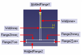
There are different section profiles for a stiffener. Each of them has different naming convention. The naming convention for detailed sections is illustrated below:
| Section Profile | Naming Convention |
|---|---|
| I-section |  |
| T-section |  |
| L-section |  |
| C-section |  |
List of Section Keys
Below is a list of section keys which can be assigned to the section profiles.
CATStrKeyForSection.Key0 = "UnknownFace"; |
CATStrKeyForSection.Key1 = "Start"; |
CATStrKeyForSection.Key2 = "End"; |
CATStrKeyForSection.Key3 = "MoldedFlange1"; |
CATStrKeyForSection.Key4 = "Flange1Toe+"; |
CATStrKeyForSection.Key5 = "Flange1Toe-"; |
CATStrKeyForSection.Key6 = "Flange1ToeInner+"; |
CATStrKeyForSection.Key7 = "Flange1ToeInner-"; |
CATStrKeyForSection.Key8 = "Flange1Inner+"; |
CATStrKeyForSection.Key9 = "Flange1Inner-"; |
CATStrKeyForSection.Key10 = "WebFlange1Root+"; |
CATStrKeyForSection.Key11 = "WebFlange1Root-"; |
CATStrKeyForSection.Key12 = "WebInner+"; |
CATStrKeyForSection.Key13 = "WebInner-"; |
CATStrKeyForSection.Key14 = "WebFlange2Root+"; |
CATStrKeyForSection.Key15 = "WebFlange2Root-"; |
CATStrKeyForSection.Key16 = "Flange2Inner+"; |
CATStrKeyForSection.Key17 = "Flange2Inner-"; |
CATStrKeyForSection.Key18 = "Flange2Toe+"; |
CATStrKeyForSection.Key19 = "Flange2Toe-"; |
CATStrKeyForSection.Key20 = "Flange2ToeInner+"; |
CATStrKeyForSection.Key21 = "Flange2ToeInner-"; |
CATStrKeyForSection.Key22 = "MoldedFlange2"; |
CATStrKeyForSection.Key23 = "Outer"; |
CATStrKeyForSection.Key24 = "Inner"; |
CATStrKeyForSection.Key25 = "WebInner"; |
Among these keys, only the following keys are used in the simplified representation of the section:
- MoldedFlange1
- MoldedFlange2
- Outer
- WebInner
Below is the simplified representation for I-Section:
Assign Keys
For identifying the web and flange separately, you need to assign the keys to simplified representation of the section and profile manually.
Open the simplified representation of a section in the Sketcher app.
In the tree, select a line.
The selected geometry is highlighted in the sketch.
Right-click the line and select Properties.
The Properties dialog box appears.
Select the Feature Properties tab.
In the Feature Name box, edit the feature name by adding a bracket and a key number.
If you have assigned the "MoldedFlange1" key to the line, it appears as Line.x(3).
Click OK.
The key parameter is assigned to the geometry.
Important:
You can select a particular face of the stiffener as a limiting element using the Alt key. |