Creating a Beam Using Beams and a Plane | |||||||||
|
| ||||||||
-
From the Function section of the action bar, click Beam
 .
The Beam dialog box appears.
 - In the Category list, select the required category.
If no dictionary is set in Data Setup, only the default category is available.
-
In the Material & Orientation tab:
-
Select the appropriate material and section for the beam.
- Select the required material reference.
- From the Standard list, select the section standard.
- From the Shape list, select the required section shape.
The Shape box is unavailable for selection when the material-section table does not have the SectionShape column, that is when you are using the resolved sections.
- From the Size list, select the required section size.
If no Resources Catalog or Resources Library resource is set in Data Setup, you can click More... to search and select the material and section references from database. If you select a parametric section reference from the database, the Size list is updated with the available sizes and then you can select the required section size.
-
In the Anchor Point list, select the required anchor point
for proper orientation of the beam.
If no molded convention resource is set in Data Setup, the default list of anchor points will be available.
-
Select the appropriate material and section for the beam.
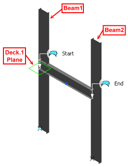
- In the Geometry tab, select Beams and Plane from the Type list.
- In the Plane box, select a plane.
- In the Beam 1 box, select a beam.
- In the Beam 2 box, select another beam.The selected beams are set as start and end limits in the Limit area.
- Optional: Under the Limits area, select the required start and end limits.
- Click OK.The beam is created.
