- Double-click the representation node in the tree.
- Create two geometrical set under the representation node and rename them.
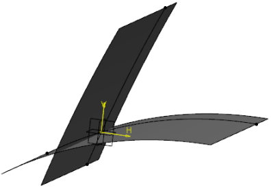
The geometrical sets, Reference Contour and Limit Surface, are created. - Under Limit Surface geometrical set, create two limiting surfaces:
- Select the xy plane.
- From the Geometrical Tools section of the action bar, select Positioned Sketch
 . .You enter the Sketcher app. - Create a spline.
-
Click Exit app
 to exit the sketcher. to exit the sketcher.
- Click Extrude
 to extrude the profile. to extrude the profile.An extruded surface is created. - Rename it as Limit 1 Surface.
- Select the xy plane.
- Repeat step (b) to (e) to create another extruded surface intersecting the previously created surface.
- Rename the other surface as Limit 2 Surface.
Two limiting surfaces are created. 
-
From the Compass, click Generative Shape Design.
You are switched to Generative Shape Design.
-
From the Transform section of the action bar, select Inverse
 . .
The Invert Definition dialog box appears. - In the To Invert box, select Limit 1 Surface.
- Click OK.
The surface is inverted. - Similarly, invert Limit 2 Surface.
-
Activate the Reference Contour geometrical set and click Positioned Sketch
 in the action bar. in the action bar.The Sketch Positioning dialog box appears prompting you to select the planar support. - Select the xy plane to create intersection of the surfaces:
You are switched to Sketcher. - From the Sketch section of the action bar, click Intersect 3D Elements
 . .The Intersection dialog box appears. - In the Element(s) to intersect box, select Limit 1 Surface.
- Optional:
Select the No Canonical Curve check box, if the use-edge is
going to be used for a face of a flange, panel, or plate selected by pressing
Ctrl or Alt.
- Click OK.
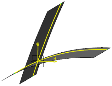
An intersection is created. For more information, see Sketcher User's Guide: Performing Operations on Profiles: Projecting 3D Elements:
Intersecting 3D Elements with the Sketch Plane. - Rename it as Limit_1.
- Repeat step (a) to (c) for Limit 2 Surface.
- Rename it as Limit_2.
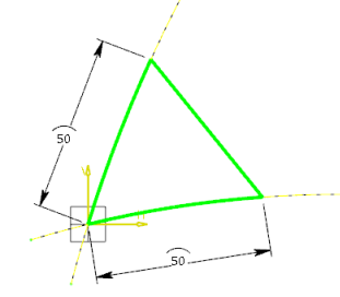
The intersection is created.  - Create a sketch on the xy plane and apply constraint to it.
-
Create an output profile:
- From the Sketch section of the action bar, click 3D Profile
 . .The Profile Definition dialog box appears. - Select the lines.
- Click OK.
The profile is created. It is recommended to define an additional output profile to be used as a support for stiffener on free edge or flange.  - Apply parameters and formulas to the sketch.
For more information about creating parameters, see Knowledge
Basics: Creating and Working with Parameters and Managing Relations: Formulas.
-
Click Exit app
 to exit Sketcher. to exit Sketcher.The contour is created. -
Select to save the contour.
The contour is saved in the database.
|
 .You enter the Sketcher app.
 to exit the sketcher.
 to extrude the profile.An extruded surface is created.
 .
.
 in the action bar.The Sketch Positioning dialog box appears prompting you to select the planar support.
 .The Intersection dialog box appears.

 .The Profile Definition dialog box appears.
 to exit Sketcher.The contour is created.
 > Save > Save with Options to save the contour.
The contour is saved in the database.