About XML Schema Files | ||||
|
| |||
XML Schemas and User Subroutines
An XML schema is a file that defines the user interface to go with a user subroutine. User subroutines allow you, as the expert user, to define what data is required to drive specialized simulations. With certain user subroutines, you define the parameters and determine their format to fit within the data lines of the solver. Defining an XML schema allows you to provide a user interface that makes it convenient for another user to enter the data or access the files that contain it. This enables that user to properly drive a simulation and achieve the desired results without directly editing data lines in the user subroutine.
For general information about user subroutines, including a list of the user subroutines available in 3DEXPERIENCE apps, see About User Subroutines. Once you create a subroutine, you can create a schema to match the data required by the subroutine to a user interface. The schema creates a custom user interface that guides a user to enter the proper data. The schema should provide labels that clearly indicate the required entries. An entry might be a single item or a table with many lines of related data. Table data could be entered in the interface but is more often imported from a spreadsheet or text file. The user subroutine takes the entries from the interface and generates the appropriate lines for the solver to process.
XML Schema Example
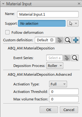
The example that follows illustrates the schema used to add data for the simulation of the material input portion of an additive manufacturing process. The Material Input dialog box is used to add data corresponding to depositing a new layer of material powder to a part being created by additive manufacturing. The data entry in the dialog box is used in the UEPACTIVATIONVOL Abaqus user subroutine.
The XML schema appears after the image.
For more specific information related to the dialog
box, see
Defining Material Input.
<UserSchema>
    <ParameterTableType name="ABQ_AM.MaterialDeposition">
        <Schema type="PLMEventSeries" name="Event Series" eventSeriesType="RollerMotion"/>
        <Schema type="enumeration" name="Deposition Process">
            <Option value="Roller"/>
            <Option value="Bead"/>
        </Schema>
    </ParameterTableType>
  <ParameterTableType name="ABQ_AM.MaterialDeposition.Bead">
    <Schema type="enumeration" name="Stack Direction">
      <Option value="X"/>
      <Option value="Y"/>
      <Option value="Z"/>
    </Schema>
    <Schema type="float" name="Bead Height" units="LENGTH"/>
    <Schema type="float" name="Bead Width" units="LENGTH"/>
    <Schema type="float" name="Activation Offset" units="LENGTH"/>
    <Schema type="enumeration" name="Deposition Position">
      <Option value="Below"/>
      <Option value="Above"/>
    </Schema>
  </ParameterTableType>
  <ParameterTableType name="ABQ_AM.MaterialDeposition.Advanced">
    <Schema type="enumeration" name="Activation Type" default="Full">
      <Option value="Full"/>
      <Option value="Partial"/>
    </Schema>
    <Schema type="float" name="Activation Threshold" units="DIMENSIONLESS" default="0.0"/>
    <Schema type="float" name="Max volume fraction" units="DIMENSIONLESS" default="0.0"/>
  </ParameterTableType>
    <EventSeriesType name="RollerMotion">
        <Schema name="On and Off" units="DIMENSIONLESS"/>
    </EventSeriesType>
    <AnalysisData>
        <TableCollection>
            <ParameterTable type="ABQ_AM.MaterialDeposition"/>
          <ParameterTable type="ABQ_AM.MaterialDeposition.Bead" linkage="ABQ_AM.MaterialDeposition" enum="Deposition Process" validValue="Bead"/>
          <ParameterTable type="ABQ_AM.MaterialDeposition.Advanced"/>
        </TableCollection>
    </AnalysisData>
</UserSchema>