-
From the Antenna Placement section of the action bar,
click Obscuration Plot
 . .
Antenna Placement tessellates the platform and computes an obscuration plot for each placement candidate.
The Obscuration Plot dialog box opens, displaying the results for
the first antenna and placement candidate. Yellow handles appear in the 3D area. The
initial range is the entire spherical view.
- Optional:
From the Antenna options, select a different antenna; or from
the Placement candidate options, select a different placement
candidate.
Antenna Placement updates the plot and blockage area results for the new antenna and placement candidate
selections.
- Optional:
From the Sector section, select a different range for evaluation
from the Angular range options:
| Option | Description |
|---|
| All |
Represents the entire far-field sphere. |
| Custom |
Represents a range of the far-field sphere that you specify. |
| Front, Back, Left, Right, Top, Bottom |
Represents the part of the far-field sphere that aligns with the corresponding
global direction (that is, +X, -X, +Y, -Y, +Z, -Z, respectively). |
-
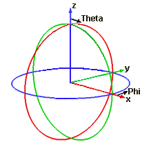
If you selected Custom from the Angular
range options, specify the range using Phi and
Theta.
Use the image below as a frame of reference.
-
Click Update.
Antenna Placement updates the plot and Blockage area (%) with the results for your
new range selection.
- Optional:
Click Reset to reset your range selections to the original
values.
The dialog box displays the initial area of evaluation for the current placement
candidate.
|