Define a Placement Candidate by Selecting Two Axis Systems
You can define a placement candidate by aligning an axis system on the antenna with
an axis system on the platform.
Before you begin: If required, create an axis system on both the antenna and the
platform. For information about automatically generated antenna axis systems using CST Studio Suite, see CST Studio Suite Antenna Projects.
-
From the Antenna Placement section of the action bar,
click Placement Candidate
 . .
- Optional:
Enter a descriptive
Name.
-
From the Placement method options, click Two Axis
Systems
 . .
If you switch placement methods, the dialog box preserves any information that you
entered in case you switch back.
-
From the Antenna options, select an antenna from the
list.
-
From the Antenna axis options, select an antenna axis from the
list.
-
In the 3D area, select
a platform axis system.
A green antenna glyph appears at the selected location, such that the two axis
systems align.
-
Check the antenna's position in the 3D area to
verify proper antenna orientation on the platform.
- Optional:
If required, modify your axis selections.
-
Click OK.
The placement candidate appears in the tree, under .
Define a Placement Candidate by Selecting an Engineering Connection
You can define a placement candidate by selecting an existing engineering
connection, which positions the antenna at the site of the engineering connection. When you
activate the placement candidate, Antenna Placement deactivates all other engineering connections and placement candidates.
-
From the Antenna Placement section of the action bar,
click Placement Candidate
 . .
- Optional:
Enter a descriptive
Name.
-
From the Placement method options, click
Engineering Connection
 . .
If you switch placement methods, the dialog box preserves any information that you
entered in case you switch back.
-
From the tree, select an engineering connection.
- Optional:
Click Preview to activate the selected engineering connection
and to perform a geometry update that repositions the antenna to the site of the
engineering connection.
Conflicting engineering connections are automatically and temporarily
deactivated.
-
Click OK.
The engineering connection activates, and Antenna Placement repositions the antenna to the site of the engineering connection. The placement
candidate appears in the tree, under .
Define a Placement Candidate Interactively
You can define a placement candidate by attaching a Robot to the antenna and then interacting with the Robot to position the placement candidate on the platform.
Before you begin: If required, create an axis system on the antenna at the
location where it attaches to the platform. For information about automatically generated
antenna axis systems using CST Studio Suite, see CST Studio Suite Antenna Projects.
-
From the Antenna Placement section of the action bar,
click Placement Candidate
 . .
- Optional:
Enter a descriptive
Name.
-
From the Placement method options, click
Interactive
 . .
If you switch placement methods, the dialog box preserves any information that you
entered in case you switch back.
-
From the Antenna options, select an antenna from the
list.
-
From the Antenna axis options, select an antenna axis from the
list.
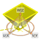
The app colors
the antenna yellow. A Robot appears, attached to the antenna at the selected axis system. For example, the image
below shows a Robot attached to a horn antenna.  -
Interact with the Robot to position the antenna on the platform.
-
Drag the Robot's origin to the platform, and slide it along the platform's surface.
The origin moves conformally on the platform's surface and briefly sticks
to nearby features, such as edges, points, and axis systems.
-
Drag the Robot's curved segments to rotate the antenna.
-
Drag the Robot's axes to translate the antenna.
-
Click OK.
The Robot disappears. A green antenna glyph appears at the selected location. The placement
candidate appears in the tree, under .
|