About Placement Candidates | ||||
|
| |||
Two-Axis-Systems Method
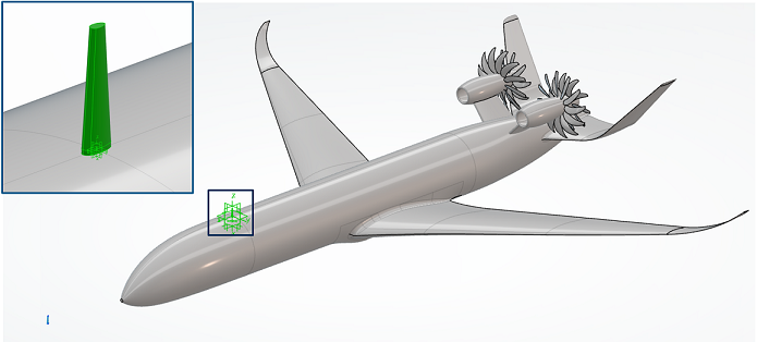
The two-axis-systems method positions the antenna such that an axis system on the antenna is coincident with an axis system on the platform. After you select the two axis systems to align, Antenna Placement displays a green antenna glyph at the installed position, as shown in the image below.

While Antenna Placement uses a glyph to display the antenna's final position, the true antenna geometry remains at the origin. The app transposes the true antenna geometry to the placement candidate location only during the simulation. If you select an antenna axis system in the 3D area, select the axis system of the true antenna, not the green antenna glyph.
You can define axis systems in a variety of ways on the 3DEXPERIENCE platform; for example, you can use Assembly Design or Part Design to define your platform's axis systems. If you used CST Studio Suite to define your antenna's geometry, Antenna Placement automatically creates axis systems from the antenna's anchor points and port pins.
After you position the antenna with the two-axis-systems method, you can use the Robot to further adjust the antenna's position. The Robot is useful, for example, to rotate the antenna or to translate the antenna offset from the platform's axis system.
Engineering Connection Method
The engineering connection method places an antenna at the site of an engineering connection feature. You can use Assembly Design to create engineering connection features on your platform. After you create the engineering connection, select the connection to define a placement candidate at that site. For more information about creating engineering connections, see 3D Modeling | Mechanical Systems | Assembly Design | Engineering Connections.
Only one engineering connection on your antenna can be active at any time, because the engineering connection repositions the antenna's true geometry. If you create several engineering connections for your antenna and then use this method to define a placement candidate, the simulation becomes over-constrained when more than one engineering connection is activated concurrently. Therefore, when the active placement candidate changes, Antenna Placement automatically deactivates conflicting engineering connections that are associated with other placement candidates.
Since the engineering connection method repositions the antenna's true geometry, you do not see a green antenna glyph on the platform.
In the tree, inactive engineering connections display masks over their icons. For more information about masks, see Tree Masks.
Interactive Placement Method
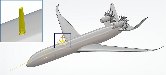
The interactive placement method attaches a Robot to the antenna; you then manipulate the Robot to position a placement candidate on the platform. The image below shows a Robot attached to an antenna, which is located at the absolute origin of your simulation.

You specify which axis system of the antenna to connect with the Robot, such that the two then move together. The Robot automatically "sticks" to the platform when you drag it by its origin onto the platform's surface. This allows the origin of the antenna's axis system to conform to the surface of the platform, which is particularly useful when the platform's surface is curved.
Once the Robot is on the platform's surface, you can interact with it to adjust the position of the placement candidate. Dragging any of the Robot's curved segments or its circular base rotates the Robot, while dragging any of the Robot's axes translates the Robot. As you drag the Robot along the platform's surface, it briefly sticks to nearby features, such as edges, points, and axis systems. This functionality improves your ability to position the placement candidate precisely on these platform features. You can also manually enter coordinates and angles, or translations and rotations, to change the location and orientation of the Robot. Using coordinates to position the Robot might dislocate it from the platform's surface.
The interactive placement method uses a glyph to indicate the position of a placement candidate. While the Robot is active, Antenna Placement displays a yellow glyph. Once you create the placement candidate, the app displays a green glyph. Since the glyph is a visualization object only, refer to the true antenna geometry (located at the absolute origin) and its axis systems to define any subsequent placement candidates.
You can combine the interactive method with the two-axis-systems method to position an antenna. You first create the placement candidate using the two-axis-systems method, and you then switch to the interactive placement method to fine tune its position.
Selective Geometry Loading and Selection Filtering
To improve performance, particularly for large platform assemblies, Antenna Placement does not fully load the antenna and platform geometries immediately after selecting them in 3DSearch. Click the geometries to load them. If you are defining a placement candidate, you must then click the geometry again to select its axis system.
As you begin to select axis systems for your placement candidate, your pointer changes to help you interact with the geometry. The table below provides the pointers displayed while hovering over your geometries.
| Pointer | Description | Meaning |
|---|---|---|
 |
Eyeball | The underlying geometry is not loaded. Click to load the portion of the geometry that includes the axis system. |
 |
Stop sign | The underlying geometry is not available for selection. |
 |
Pointing hand | The underlying geometry is available for selection. |
In addition to clicking geometry to load it, you can also load the geometry by expanding the tree to reveal the axis system. Once the geometry loads, the pointer changes into a pointing hand to indicate that an underlying axis system is available for selection.
When selecting the antenna's axis system, an interactive selection filter ensures that you select a valid axis system. This filter permits you to select only those axis systems associated with the antenna. When selecting the platform's axis system, a similar filter ensures that you select only those axis systems associated with the platform. If you hover over an invalid axis system, the pointer changes into a stop sign.