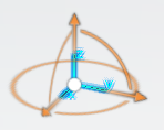
Create Markers Manually
You can create a marker using an axis-system as its origin, and by specifying its
position and orientation manually.
-
From the Mechanism section of the action bar, click Marker
 . .
-
In the tree, select a body on which to create the marker.
-
Select Manual
 as the type of
marker to create. as the type of
marker to create.
The marker appears in the tree, under the Body

node. -
In the Position and Orientation section of the dialog box,
define the marker:
-
Enter a position value for the element along the x, y, and z-axis.
-
Select one of the following rotation sequences:
- Extrinsic: Rotations that apply to an axis in
the world coordinate system. The orientation follows the x, y, and
finally the z-axis.
- Euler: Three angles that describe the
orientation of a rigid body with respect to a fixed coordinate
system. The orientation follows the z, x', and finally the
z"-axis.
- Cardan: Rotation sequence from angular
orientation data. The orientation follows the x, y', and finally the
z"-axis.
-
Specify a value for each orientation angle.
-
Click OK
Create Markers Using a Geometric Element
You can create a marker using a geometric element as its origin. The position and
orientation of the marker depends on the selected geometry.
-
From the Mechanism section of the action bar, click Marker
 . .
-
In the tree, select a body on which to create the marker.
-
Select By Geometry
 as the type
of marker to create. as the type
of marker to create.
- Optional:
In the tree, select the geometry to use to define the origin of the marker.
Note:
You can select one of the following geometric elements:
- Axis-system
- Point (vertex)
- Line (linear edge)
- Circular edge
- Conical face
- Cylindrical face
- Planar face
- Spherical face
Note:
If you select no geometry, the default origin is the reference marker
of the body.
The position and orientation of the marker along the x, y, and z-axis appear
in the Position and Orientation section of the dialog box. Note:
You cannot edit the position and orientation values but you can display
them according to a different rotation sequence.
-
In the Axes section of the dialog box, define the direction of
the marker along the x, y, and z-axes.
-
Select a primary axis to define the main direction of the marker.
- Optional:
Click Flip primary axis direction
 to reverse
the direction of the geometry along the primary axis. to reverse
the direction of the geometry along the primary axis.
- The Robot displays the new direction of the axis in the 3D area.
- The position and orientation of the marker is updated in the
Position and Orientation section of the dialog box.
- Optional:
In the work area, select a geometry for each axis.
The selected geometry defines the direction of the marker along the axis. You
can select one of the following geometric elements:
- Line (linear edge)
- Circular edge (arc)
- Planar face
- Cylindrical face
- Conical face
- Axis from an axis system
- Reference plane
- Reference axis
Note:
By default, if you select no geometry for one or several of the
axes, the app
computes the direction of the axis or axes.
-
Optional: Click Flip direction
 to reverse
the direction of the geometry selected for each axis (other than the primary
axis). to reverse
the direction of the geometry selected for each axis (other than the primary
axis).
- The Robot displays the new direction of the axis in the 3D area.
- The position and orientation of the marker is updated in the
Position and Orientation section of the dialog box.
-
In the Offset section of the dialog box, define the offset
position and orientation of the marker:
-
Enter a position value for the element along the x, y, and z-axis.
-
Select one of the following rotation sequences:
- Extrinsic: Rotations that apply to an axis in
the world coordinate system. The orientation follows the x, y, and
finally the z-axis.
- Euler: Three angles that describe the
orientation of a rigid body with respect to a fixed coordinate
system. The orientation follows the z, x', and finally the
z"-axis.
- Cardan: Rotation sequence from angular
orientation data. The orientation follows the x, y', and finally the
z"-axis.
-
Specify a value for each orientation angle.
The position and orientation of the marker is updated in the
Position and Orientation section of the dialog box. Note:
You cannot edit the position and orientation values, but you can display
them according to a different rotation sequence.
-
Click OK.
Edit Markers
-
In the tree, double-click a marker under a body.
-
In the Marker dialog box, edit the marker parameters.
-
Click OK.
Note:
To modify the general properties or graphical properties of the element, right-click the element in the tree and select Properties. For more information, see Displaying Properties.
|
 .
.
 as the type of
marker to create.
The marker appears in the tree, under the Body
 node.
node.