About Weld Fillet Sets | |||||
|
| ||||
The requirements and capabilities of weld fillet sets depend on the type of durability simulation in which you define them.
Weld Fillet Sets in Durability Analysis Cases
For weld fillet sets in a Verity simulation, the locations you specify must be modeled as part of the CAD geometry. In addition, the meshes between the fillet and the plates must use face capture with the condensation method to ensure nodes are shared and not duplicated.
For shell models, you can use line fasteners defined in the Structural Model Creation app as the support for weld fillet sets.You can simulate multiple weld failure modes (such as toe failures and throat failures) in the same analysis, or you can simulate the subset of weld failure modes that you want.
Weld Fillet Sets in FKM Analysis Cases
When you define a new weld fillet set in an FKM simulation, the app populates its parameters using the parameters in its parent FKM assessment. However, once the weld fillet set has been created, changes to the parameters in its parent FKM assessment do not change the parameter values in the weld fillet set.
Weld fillet set parameters in an FKM simulation propagate from assessment to assessment until you change their values. This propagation follows a similar pattern to the way the loads and boundary conditions propagate from step to step in structural analysis cases.
Acceptable Configurations for Shell Weld Fillet Sets
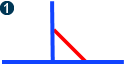
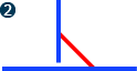
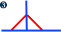
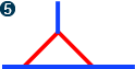
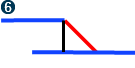
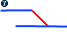
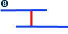
Durability simulations support a set of 10 weld fillet set configurations for shell models. The acceptable configurations for weld fillet sets in shell models of welds appear below. In each model, red angled lines show the weld fillet geometry. Except for configuration 8, the weld fillets are drawn at 45 degrees, but they can vary by up to 22.5 degrees from the ideal shapes shown below.
 |
 |
 |
 |
 |
 |
 |
 |
 |
 |