Define the Contact Interactions | ||
| ||
-
Change the analysis context to Global Analysis.

The analysis context changes when you create or edit an analysis case, step, or feature. When you created the submodel analysis case, the context changed from Global Analysis to Submodel Analysis. Therefore, you must change the analysis context back to Global Analysis before you can define the contact interactions in the global model. -
From the Interactions section of the action bar, click Surface-based Contact
 .
.
-
Define the contact interactions for the parts in the submodel analysis
case.
- Name the contact Sprocket to Hollow Shaft.
- Select Let system determine main/secondary assignment.
- For the Main support, change the selection method to Publication.
-
From the Publication selection menu, select the publication called
Sprocket_Sprocket to Hollow Shaft and click
OK.
The publications follow the naming convention Part A_Part B to Part C. The surface associated with the publication belongs to Part A. You use the publication to define a contact interaction between Part B and Part C.
The app highlights the surface associated with the publication in green .
.
- For the Secondary support, change the selection method to Publication.
-
From the Publication selection menu, select the
publication called Hollow Shaft_Sprocket to Hollow
Shaft and click OK.
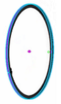
The app highlights the surface associated with the publication in magenta
 .
.
- Accept the default penalty contact property.
-
Select Tie surfaces and Within
specified tolerance.
Leave the tolerance field empty.
- Click OK.
-
Similarly, define the contact interactions for the remaining parts using
publications to select the contacting surfaces, as described in the following
table:
Name Contact Interactions Hollow Shaft to Distance Washer 1 The inner ledge of the hollow shaft (publication name: Hollow Shaft_Hollow Shaft to Distance Washer 1) to the adjacent flat face of the distance washer (publication name: Distance Washer_Hollow Shaft to Distance Washer 1). 

Hollow Shaft to Distance Washer 2 The inner wall of the hollow shaft (publication name: Hollow Shaft_Hollow Shaft to Distance Washer 2) to the outer surface of the distance washer (publication name: Distance Washer_Hollow Shaft to Distance Washer 2). 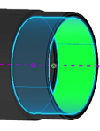
Distance Washer to Bearing The flat face of the distance washer (publication name: Distance Washer_Distance Washer to Bearing) to the adjacent face of the bearing's outer race (publication name: Bearing_Distance Washer to Bearing). 
Bearing to Hollow Shaft The outer surface of the bearing's outer race (publication name: Bearing_Bearing to Hollow Shaft) to the inner wall of the hollow shaft (publication name: Hollow Shaft_Bearing to Hollow Shaft). 
Bearing to Support Shaft The inner wall of the bearing's inner race (publication name: Bearing_Bearing to Support Shaft) to the surface of the support shaft (publication name: Support Shaft_Bearing to Support Shaft_Bearing Stopper to Support Shaft). 

Bearing to Bearing Stopper The flat face of the bearing's inner race (publication name: Bearing_Bearing to Bearing Stopper) to the adjacent face of the bearing stopper (publication name: Bearing Stopper_Bearing to Bearing Stopper). 

Bearing Stopper to Support Shaft The inner wall of the bearing stopper (publication name: Bearing Stopper_Bearing Stopper to Support Shaft) to the surface of the support shaft (publication name: Support Shaft_Bearing to Support Shaft_Bearing Stopper to Support Shaft). Note: You use the second publication to define two different contact interactions. The name of the second contact interaction is appended to the publication name.
-
Create identical contact interactions for the submodel analysis case.
Important: Do not use publications to select surfaces for the contact supports. Instead, select the surfaces manually. Tips: To select the surfaces, you can: - Use the tree to hide parts (that is, right-click a part, and select
Hide/Show
 .)
.) - Use the digger to temporarily hide parts behind the pointer. For more information about the digger, see Simulation | Multidiscipline and Multiscale | Physics Simulation Fundamentals | Simulation Display | Hiding Objects Temporarily.
- Use the tree to hide parts (that is, right-click a part, and select
Hide/Show
-
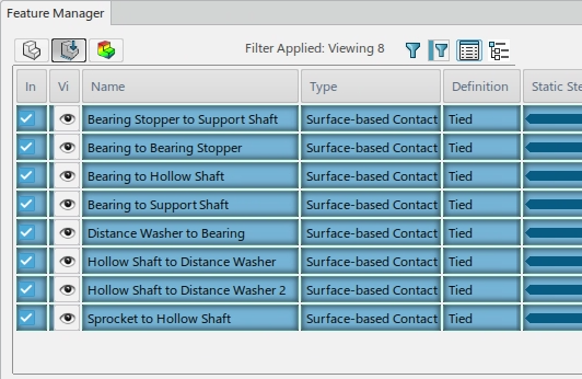
Open the Feature Manager to confirm that you created all of the contact interactions required for the
submodel analysis case, as shown in the image below.