-
From the Assistant, click Model.
The Finite Element Model dialog box
appears.
-
From the Model options, select
Create to create a finite element model (FEM).
-
Name it Coolant Mesh, and click
OK.
Coolant Mesh A.1 appears in the tree.
-
From the Model section of the Assistant, click Model Setup
 . .
-
Apply the material definition for water to the fluid section associated with
the fluid domain.
-
Click
 to open the Material Palette. to open the Material Palette.
-
From the Material Palette, search for
MynameEXAMPLE-Water.
-
Select MynameEXAMPLE-Water,
and click OK.
The app applies the material definition to the fluid section and closes the
Material Palette.
-
Expand the Fluid domain bounding parts section, and
confirm that all four parts are selected.
-
Specify the region that contacts the fluid.
-
Expand the Regions section.
-
Select the interior surface inlet nozzle.
A glyph of a blue cube with a stem  appears on that surface. 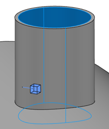
-
Select or clear Flip direction
 to ensure that the cubical portion of the glyph is immersed inside
the fluid region. to ensure that the cubical portion of the glyph is immersed inside
the fluid region.
-
Define the openings.
-
Click
 in the Openings
section. in the Openings
section.
-
Select the inner edge of the inlet nozzle.
A blue circular glyph appears in the center of the
opening. 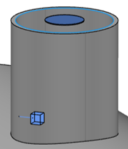
-
Similarly, add an opening for the outlet nozzle.
-
Click OK.
|