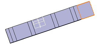
Create an Extrusion
You can create an extrusion.
-
From the Model section of the action bar, click Extrusion
 .
.
-
Select the sketch or the planar profile in the
3D area.
It appears in the Profile box.
-
Select the profile positioning option:
Option Description  Bottom
Sets the sketch at the bottom position of the wall thickness.  Middle
Sets the sketch at the middle position of the wall thickness.  Top
TopSets the sketch at the top position of the wall thickness. - Optional:
Select a fixed element in the Fixed Area box.
It can be a border vertex or an edge of the profile.
-
To define both limits, specify the limit type.
Option Description Dimension Generates the extrusion using a length. Up to plane Generates the extrusion up to the defined plane. Up to surface Generates the extrusion up to the defined surface. Mid plane Generates the extrusion using a length that is equally divided between both limits of the extrusion. It is available only with Limit 1. If the limit is set to Dimension, you can click Mirrored Extent
 to extend the material on both sides of the sketch. In
that case, only Limit 1 can be edited.
- Optional:
To invert the direction of the extrusion, click
Invert Direction
 .
.
- Optional: In the Bends frame, select With Bend.
- Optional:
Select the unfold method, and specify its parameters:
Option Description K-factor Defines the neutral fiber position inside the thickness, from the inner side of the bend. Bend Allowance The bend allowance corresponds to the unfolded bend width. Bend Deduction The bend deduction represents the sheet metal deformation when the bend is unfolded. Bend Table from Standards Uses the bend deduction table defined in the standards. You must select a standard containing a bend deduction table. Note: The Bend Table from Standards unfold method is automatically selected if a bend table is defined in the Sheet Metal parameters. If you do not want to use this unfold method, you can choose another standard in the Sheet Metal parameters that does not contain a bend deduction table. For more information, see Editing the Sheet Metal Parameters. - Optional:
Select one of the following for each bend extremity:
If you create a feature on the extruded profile, the bend extremities may be recomputed to ensure a consistent result.
Option Description Minimum with no relief The bend corresponds to the common area of the supporting walls along the bend axis, and shows no relief. Square relief The bend corresponds to the common area of the supporting walls along the bend axis, and a square relief is added to the bend extremity. The Length 1 and Length 2 parameters can be modified if needed. Round relief The bend corresponds to the common area of the supporting walls along the bend axis, and a round relief is added to the bend extremity. The Length 1 and Length 2 parameters can be modified if required. Linear The unfolded bend is split by two planes going through the corresponding limit points (obtained by projection of the bend axis onto the edges of the supporting walls). Tangent The edges of the bend are tangent to the edges of the supporting walls. Maximum The bend is calculated between the furthest opposite edges of the supporting walls. Closed The bend corresponds to the intersection between the bends of the two supporting walls. The closed bend extremity lies on the surface of the encountered bend. Flat joint The two bends are joined in flat view.


