Displaying Continuities On Elements

You can display continuities on elements and modify their values.

These handles appear:

  • either by clicking the command in the App Options panel as illustrated in this task
  • or by selecting the option in Me > Preferences > App Preferences > 3D Modeling > Styling > FreeStyle Shape Design, General tab, Display section.
Once they appear, their behavior is identical regardless of the chosen interface style.

The continuity types available are:

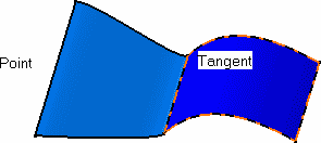
  • Point continuity: the elements share each point of their common boundary, i.e. there is no gap between the elements
  • Tangent continuity: the elements share a common tangent plane (i.e. normal) at each point of their connection
  • Proportional: similarly to the Tangent option, surfaces share a common tangent plane (i.e. normal) at each point of their connection, but the longitudinal variation from one point to the other is smoother, as the system automatically re-distributes the control point location on the blend surface. This mode is automatically set for both limits of the blend surface.
  • Curvature continuity: the elements share a common curvature and tangent plane at each point of their connection.


Before you begin: Open an existing 3D shape.
See Also
Displaying Contact Points On Elements
Displaying Tensions On Elements
Displaying U and V Orders on Elements
  1. In the App Options panel, click Continuity
    Continuity type indicators indicating the continuity type are displayed wherever available.


  2. To change a continuity constraint do one of the following:
    • Click the continuity identifier.

      The continuity type changes with each click.

      If required, shift-click to reverse direction.

    • Right-click a continuity identifier and select a continuity type.

    In some cases the chosen type of continuity is not compatible with the geometry or the modification. In this case, a warning is displayed directly onto the geometry at the location where the inconsistency arises. You can then change the continuity, or modify the geometry itself. A forbidden sign may be displayed and the system will prevent you from modifying the element in a specific direction if it is geometrically incorrect.