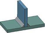
Creating a Fillet Weld | ||
| ||
-
From the Weld section of the action bar, click Fillet Weld
 .
.
-
Select both of the faces to join.
Tips: - To add or remove faces defining the supports (as displayed in the Supports list), press Ctrl + Click.
- You can add to or remove faces from a support using
the
Edit selection
context menu
from the
Supports list.
- Clicking a face in the work area adds it to the list.
- To remove a face from the list, use Remove selection.
-
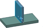
Optional: Click
Preview.
The fillet weld section appears and the edge where it will be propagated is highlighted.

-
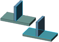
To create another weld, select the following face as support.
-
Click
Preview.
The fillet weld sections appear. The edges where they will be propagated are highlighted.
-
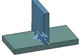
To specify the weld size, select an option:
- Throat: Defines the throat length. The a
symbol represents the throat.

- Leg Length: Defines both leg lengths.
The z symbols represent the legs.

To assign a distinct value to Leg 2, first select Leg Length 2.
- Throat: Defines the throat length. The a
symbol represents the throat.
-
Optional: To define the shape of the weld, click the
Manufacturing tab and select an option. The shape
defines the weld seam shape representation in drafting context. If you select
Convex
 or
Concave
or
Concave
 , specify a curvature value in
Offset.
The offset is the maximum distance between the weld
face and arc.
, specify a curvature value in
Offset.
The offset is the maximum distance between the weld
face and arc.
For more information about manufacturing options, see Manufacturing.
Note: Shapes are extracted on drawings. -
Click
OK.
The fillet weld is created. It appears with aggregated supports and external references in the tree.