3D Design
| Important: The information defined in the 3D Design tab of a weld is not taken into account for the manufacturing. Verify yourself the relevance of the information. |
Supports
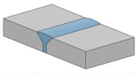
A weld feature is defined by supports. These supports are sets of faces geometrically connected or not.
Two supports at least are if required to define the weld and a linear intersection must exist between these two supports. The linear intersection is named weld design.
Guide and Seam
To each weld domain corresponds a unique seam. According to the guide continuity, the following cases are taken into account:
- For the continuous G1 domain, the seam is built from the weld guide and the seam profile.

- For the discontinuous G1 domain, the seam is divided in unitary seams as many as continuous G1 domain.
Unitary seams are trimmed from each other.

When the weld guide is closed, the seam is also closed.
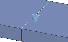
Extrapolation
A weld can be extrapolated, but only for an opened mono-domain and a mono-guide.
The weld is trimmed by the normal plane perpendicular to the guide, at the point intersecting the guide and the side face of the plate.

The preview displays white dots indicating the extrapolation limits.
The extrapolation allows you to extend the seam length outside the plate.

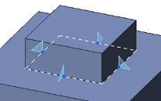
Limits
A weld without limits has natural borders corresponding to the extremity planes of the weld guide.
When these natural borders do not fit the user's needs, surface limits can be defined for the weld from Generative Shape Design surfaces. The limit you select must consist of a single planar geometric element.
| Important: A weld can be trimmed by another weld only when these welds belong to the same bundle of welds. |
- The surface limits can intersect the weld guide only once.
- The surface limits can be predefined or created in context.
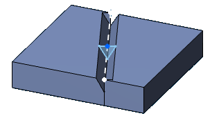
From the previous example in the extrapolation section, the seam has been trimmed by planes tangent to the side faces of the plate.

Ensure that the limit orientations must be matter side oriented. To do this, click the green dot
and then, click Flip
 in the context toolbar.
A weld can be trimmed or extended to complete another weld shape of the same type, but not necessarily with the same specifications.
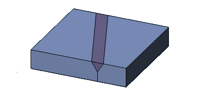
Preparation
A groove weld requires to prepare welded 3D shapes before the welding process.
The preparation is automatically taken into account during the update operation, and the weld impact  icon appears in the tree on the body of prepared 3D shapes.
| Important: The user-defined weld allows you to create your own design that will be applied for the preparation. |