-
From the Weld section of the action bar, click V-Butt Weld
 . .
-
Select a weld body in the
tree.
-
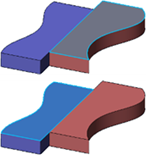
Select the following faces as supports.
- Optional: To trim the weld to a surface or another weld, select the limits.
- Optional: Change the angle value for the weld.
- Optional:
Increase the thickness.
- Optional: To extend the weld, enter a value in Extrapol Length.
- Optional:
Click
Preview.
The V-Butt weld section appears. The edge along which it will
be propagated is highlighted.

-
Optional: To define the shape of the weld, click the
Manufacturing tab and select an option. The shape
defines the weld seam shape representation in drafting context. If you select
Convex
 or
Concave or
Concave
 , specify a curvature value in
Offset.
The offset is the maximum distance between the weld
face and arc. , specify a curvature value in
Offset.
The offset is the maximum distance between the weld
face and arc.
For more information about manufacturing options,
see
Manufacturing.
Note:
Shapes are extracted on drawings.
-
Optional: Select
Generate Weld Impacts.
The app performs a Boolean subtract of the weld shape from the
plates being welded.
-
Click
OK.
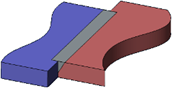
The V-butt weld is created but the affected representations are not yet prepared for
the welding. 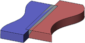
-
Click
Update
 . .
The affected representations are prepared for the welding.
- The v-butt weld appears in the tree.
- Its supports and their external references appear under the
V-butt weld.
- External references appear under the
External References node too.
- An assembly protected weld preparation is created and appears under the
Assembly features
 node. node.
- The welded 3D shapes are prepared.
|
 appears as a feature in the PartBody including
impacted 3D shapes. A rep impact
appears as a feature in the PartBody including
impacted 3D shapes. A rep impact  is created, maintaining a link between the root
product under which the bundle of weld, weld body, and welds are created.
Rep impact appears under Impacts manager
is created, maintaining a link between the root
product under which the bundle of weld, weld body, and welds are created.
Rep impact appears under Impacts manager
 .
.