Manipulating Items along with Detecting Clashes | |||||
|
| ||||
-
Right-click in the work area and
select , then click Clash Detection
ON
 .
Not to view the clash select the Clash Detection OFF
.
Not to view the clash select the Clash Detection OFF .
. -
In the Instruction Authoring section of the action bar,
click Manipulate
 .
The Manipulation panel appears.
.
The Manipulation panel appears.You can:
- Drag along any axis
- Drag along any plane
- Drag around any axis
Translate or rotate components using one of the following options:
- The first and second horizontal rows are reserved for translations. You can move your component along the x, y or z-axis as well as in the xy, yz, and xz planes.
- The third row is dedicated to rotations. You can rotate your component around the x, y or z-axis.
- The fourth column lets you specify the direction of your choice by selecting a geometric element. This element defines the direction of the move or the axis of rotation.
- There are two options and their statuses are persistent when you exit the session:
- Free manipulation: this option allows you to freely
move the selected component in the default plane only (all other iconic options
are disabled when selected.) You cannot freely rotate the component.
The default plane is define by the current view (top, bottom, left, right, back, front, iso).
Note: The default plane is the plane of the screen for the iso view. - With respect to constraints: this option allows you to
move or rotate the selected component by respecting its assembly
constraints.Note: With this option, the following component orientations in the engineering connection are not accounted for: Position first component or Position second component.
- Free manipulation: this option allows you to freely
move the selected component in the default plane only (all other iconic options
are disabled when selected.) You cannot freely rotate the component.
-
Create a View:
- Click Create View for Operation
 .
. - Click Create View with Specified Area for Operation
 .
.
- Click Create View for Operation
-
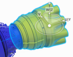
Use the Robot to move items.
If two objects are in clash, the objects in clash become highlighted.