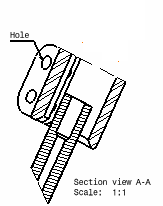
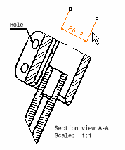
- Double-click the section view.
- From the View Layout section of the action bar, click Clipping View Profile
 to create
a clipping view using a sketched profile as callout.
to create
a clipping view using a sketched profile as callout.To create a clipping view using a circle as a callout, click
Clipping View  . . - Select the required points for sketching a polygon.
If you are creating a clipping view using a circle, select the center of
the circle.
-
Close the polygon, or double-click to end its creation.
If you are creating a clipping view using a circle, Move the pointer to
define the clipping profile, then click to validate. The
view and the associated profile result are as shown below:

Note:
The existence of dimensions that are associated with a geometrical element
that is not visible in the clipping view: these dimensions are placed in the
no-show space. (When applicable, this is also the case of annotations that
are associated with such a dimension, and of annotations that are no longer
linked to the clipping view.) For more information, refer to View.
- From the View section of the action bar, click Swap visible space
 . .
You can now visualize the dimensions (and annotations, when
applicable) that no longer appear on the clipping view.
- Optional:
You can show these dimensions again on the clipping view. To do so, click
Hide/Show
 , from the
View section of the action bar. , from the
View section of the action bar.
- Select the dimension you want to show on the clipping view.
- Click Swap visible space
 again.
 The selected dimension now appears on the clipping view again.

Note:
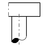
While creating a clipping view profile, an S break symbol is created at the limit
edges of the cylindrical elements only. For this, the GVS parameters must be
defined. For more information, see Break.
|
