-
Perform either of the following operations in the View Layout
section of the action bar:
- To create a circular detail view, click Detail View
 . .
- To create a detail view using a sketched profile, click Detail View
Profile
 . .
In the
Creation Options panel, you can select the graphic
properties and the operator specifications that you can propagate to this view
from its reference view. If the
Disable generative view style usage check box is
cleared in
tab, then you can also apply the available generative view styles to this view.
For more information, see
Creating a View using Generative View Styles. In this scenario, lets create a circular detail
view.
-
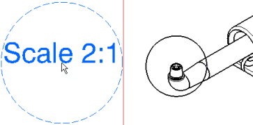
Click to position the callout center.
If you are creating a detail view using a sketched profile, create the required points
for sketching a polygon.
- Move the pointer to increase the callout radius and click to validate.
If you are creating a detail view using a sketched profile, double-click to end the
cutting profile creation. Note that if you do not close the
profile, it is closed automatically.

-
Optional: Select the 2D generative edge in this view to create an
associative detail profile.
A message appears at the upper-right corner of the screen informing that the
detail view is now associated with the selected generative item. For more information, see
About Detail
Views. -
Click in the sheet to generate the detail view.
The associative detail view is created and the message
disappears automatically once you indicate the location of the resultant detail view by
clicking at the appropriate location in the sheet. Note:
The default value of scale is 2 (twice the scale of the active view). You can modify this scale from the
Properties dialog box.
-
To modify the scale, right-click the detail view and select
Properties.
-
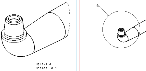
Under the View tab, in the Scale box,
enter a scale, for example 3:1.
-
Click OK to validate.
Note:
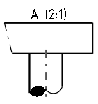
While creating a detail view profile, an S break symbol is created at the limit edges of
the cylindrical elements only. For this, the GVS parameters must be defined. For more
information, see Detail.
|


