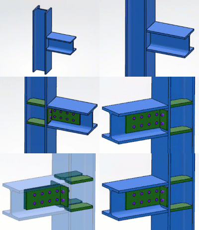
-
From the Assembly section of the action bar,
click Regular Connection Assembly
 .
.
-
In the Regular Connection Assembly dialog box, enter a name for
the connection assembly in the Name box.
-
In the Input box, click
 and specify
the input members.
-
Click Add Input
 .
.
-
In the Object cell, select a member from the tree or the 3D area.
-
In the Components box, click
 and specify
the connection components.
-
Click Add Component
 or
or  , and select a
component from a catalog or a library.
- Optional:
Edit the component, if required. To do so, select the object cell, click
 , and
select Edit Component
 .
.
- Optional:
Edit the position of connection plate and hole components. To do so, select the
object cell, click
 , and
select Edit Position
 . For more information, see Positioning Components.
- Optional:
Modify the public parameters of the components using the Parameter
Editor
 command
available in the toolbox.
-
For connection weld and hole components, specify the elements connected by them.
For more information, see Specifying Connected Elements.
-
Click OK.
-
Add the connection assembly (root product) to a catalog or a library.
For the sample files, see 3DEXPERIENCE
Native Apps Content Reference Guide: Steel Connection Design.

