Level Selector
The level selector is accessed by clicking the Level
Selector
 from the
context bar when you select a single element in the model or when you use the robot.
It is also available in the Examine Selection command.
See Level Selector in Examine Selection command.
from the
context bar when you select a single element in the model or when you use the robot.
It is also available in the Examine Selection command.
See Level Selector in Examine Selection command.
When level selector is used from a selection of a single element in the model, the Level Selector command changes selection and modifies the move level.
When level selector is used from the Robot, it changes selection and modifies the Robot orientation according to the selected level. It does not modify the move level.
Moving along the graduation from left to right lets you explore the structure of the model and select object at a specific level:
- Each graduation mark (also referred to as a bar) corresponds to a level in the model's structure from the leaf element up to the parent level.
- When you hover over a graduation mark, the active structure level is
highlighted and the name of the element is displayed in a label.

- To select the target level element, click a graduation mark.
- Dynamic highlighting in the 3D also provides feedback about the current level and particularly which objects belong to this level.
- If you select an element that is the parent element of the model (for example the root element), the level selector command is not available.
A filtered structure can be navigated from the 3D using the level selector. If the
structure has been filtered using 6WTags and you have applied colors, the
Level Selector
indicates the
different structure levels using the defined colors. For more information, see Selecting a Structure Level.
Level Selector in Examine Selection command
When using the Examine Selection command, a level selector is permanently displayed on the top right corner of the work area, if only a single assembly component is selected. Unlike the contextual level selector, it does not change the selection but the move level. Consequently, levels corresponding to components which position cannot be stored in the 3DEXPERIENCE platform cannot be selected and are grayed out in the level selector as they cannot be specified as "move level"
It allows you to identify the move level that will be accounted for if a geometry of the examined component is dragged and snapped. The name of the current move level is permanently displayed unless you hover another bar of the level selector. You can use the level selector to change the move level without exiting the Examine Selection command.

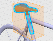

 , the box is recomputed according to the selected elements
visible in this space. If there is no element in this space, the box is not visible.
, the box is recomputed according to the selected elements
visible in this space. If there is no element in this space, the box is not visible.