Rotate the Object's Viewpoint
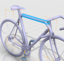
An orange bounding box helps you visualize the move level corresponding to an
object and is displayed around the parent object when a component selected. You can drag
the bounding box to rotate the viewpoint of the objects you are about to move.
-
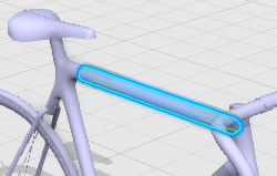
Select the component you want to move. In this example, select the top
tube.
- If you are using the Examine Selection
functionality and you start the Section or
Measure commands, the
Move operation is not stopped. Therefore,
its is not necessary to save the object's position into the database
before.
- A filter bar appears to filter the geometry selection.
- A context toolbar appears along with the bounding box around the selection.
- The top tube component belongs to the frame.
- The frame is highlighted in the scene and the move level is set to
frame:
- Optional:
To filter the geometry selection, select one of the following options in the
filter bar.
| Option | Description |
|---|
 Point
Point
|
Highlights points you can select directly (either an existing point
on the model, or any point you click on the model).
|
 Center/Point
|
Highlights the coordinates of the center point of a circle, or a
sphere, or the coordinates of the selected point. You can only
select center points.
|
 Axis* System
|
Highlights the X, Y, and Z direction coordinates of local axis
systems. You can only select axis systems.
|
 Line
Line
|
Colors lines in blue. You can only select lines.
|
 Plane*
 |
Colors in blue the area of a planar surface. You can only select
planar surfaces.
|
 Cylinder/Cone*
 |
Colors in blue a cylinder or a cone. You can only select cylinders or
cones.
|
 Surface Surface |
You can select any kind of a surface.
|
 Product*
 |
Displays the volume of the bounding box containing the selected item.
You can only select whole products. A level selector is available to
select objects at a specific level.
|
Notes:
- By default, the filters are not visible until you click the
Manipulate
 command from the action bar or drag the Robot. command from the action bar or drag the Robot.
- *By default, axis system, plane, cylinder and product options are
turned on. To refine your selection, choose the most appropriate
option.
- All options are cumulative options that can be combined.
- By default, only axis system, plane, cylinder/cone and product
filters are active.
- For all the filters except the Surface
and Product
filter, the high quality representation of
the selected geometry is loaded in the session.
-
Select the bounding box.
The selection instanced under the move level is colored in orange to
help you visualize the objects you are about to move:
- The top tub (the component you previously selected) and
- The frame (the parent object to which the component belongs)

-
Drag a bounding box handle to rotate the viewpoint according to the
pointer position.
The selection is set to full opacity while the rest of the model is
set to semi-transparent opacity. At the end of the manipulation, the
viewpoint is automatically reset to its initial orientation. 
- Optional:
Change the move level definition to top_tube. To do
so:
- Select the level selector and
- Click the bar of interest.

The selected component is changed accordingly and highlighted. It becomes
the reference for the move level.
Move by Dragging
You can move objects directly by dragging them onto other objects. The axis
system of the origin component is used to place the component onto the target component.
-
From the Edit Structure section of the action bar, click Manipulate
.
-
Drag a component toward a second component.
If axis systems are detected, they are identified and let you snap the
component.
The moved
component becomes transparent. When finished dragging the component, the
position can be modified, a notification lets you confirm the move
operation and save the modification.
-
Validate or continue the move operation:
- Click Cancel to place the component in its
original position.
- Click OK to save the new position of the
component.
For more information, see Controlling Editability during a Move Operation.
- Optional:
Open the data of only one platform within the same app. When you switch platforms, the previously edited data are cleared.
You define the platform and security context options
with the Preferences command.
The component is moved accordingly. Note:
You can move several components at a
time or successively.
Reset to Local Coordinates
This command lets you remove any positioning information for the selected
component instances to ensure they can be considered as designed in their parent product
axis systems. This command is helpful to correct any unexpected move.
-
Move a component.
-
In the context toolbar, click

The component is moved back to its original position.
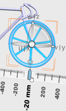
Use the Robot
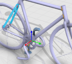
You can move objects using the Robot and the ruler.
-
Select the Robot's origin and then drag it onto an object.
For line, surface, cylinder, cone, plane, and product, a temporary
representation is displayed while snapping the Robot.
The Robot is snapped onto an object. 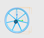
-
Use the axes or arcs to move or rotate.
-
Use the ruler to position precisely your object. The graduations help
translating or rotating the object by snapping on specific values.
-
To change the ruler's origin, select the ruler origin manipulator
 . .
You can change the ruler origin for all the translation axes of the Robot to move selected products according to this new origin. As the ruler
displays the values according to this new defined origin, you can check
distances regarding other faces, and you do not need to measure a distance
after using the Robot.
| Selected Items | Description of the new ruler origin |
|---|
| Planes are considered only if they are perpendicular to the
translation axis. |
The new ruler origin is set at the intersection of the plane and
the translation axis |
| Cylinders and cones are considered only if their axis are
perpendicular to the translation axis. |
The new ruler origin is set at the orthogonal projection of
cylinder axis on the translation axis. |
| Circles are considered only if circle plane normal is
perpendicular to the translation axis. |
The new ruler origin is set at 0 value is set at the orthogonal
projection of circle plane normal going through circle center on the
translation axis. |
| All spheres are considered. |
The new ruler origin is set at the orthogonal projection of the
sphere center on the translation axis. |
| All points are considered. |
The new ruler origin is set at the orthogonal projection of the
point on the translation axis. |
| All parts are considered. |
The new ruler origin is set at the orthogonal projection of part
axis origin on the translation axis. |
| All axis systems are considered. |
The new ruler origin is set at the orthogonal projection of axis
system origin on the translation axis. |
| Any other geometric element cannot be used to defined a new
ruler origin. |
- |
-
Drag the ruler origin manipulator anywhere in the 3D area.
Notes:
- If the ruler origin manipulator is dragged over nothing, it
remains at the position where the Robot was dropped even if a new ruler origin has been previously
defined.
- If it is dragged over a valid geometry, product or axis system,
it is moved to the new origin position.
- If it is dragged over a not valid geometry, product or axis
system, it remains at the position where the Robot was dropped.
- Any usage of Robot rotation manipulators will reset any ruler origin defined on
translation axis.
- Any usage of Robot plane manipulators will not reset any ruler origin defined on
translation axis.
The components are moved accordingly.
|