About Connections | ||||||
|
| |||||
A default Connection.1 is automatically assigned to every layer stacking.
Connection Types
In general, there are three conceivable welding types for a flange connection:
- Spot welds
- Laser welds
- Adhesive
- Point Fastener
- Line Fastener
- Surface Fastener
| Spot welds | Point Fastener |
| Laser welds | Line Fastener |
| Adhesive | Surface Fastener |
Automated Computation of Spot Weld Positions
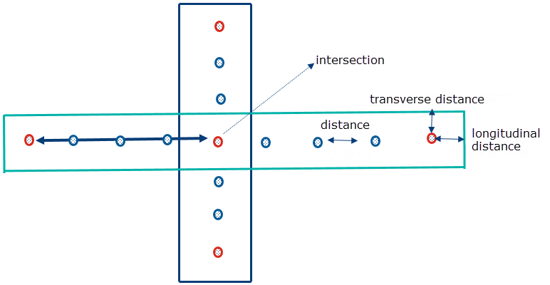
Concept Structure Engineering calculates the positioning automatically. The figure illustrates the important positioning attributes, such as distance and longitudinal offset. Red points denote the fix points where the spots are created first. Such fix points are created mainly using two criteria:
- Intersection of two flanges with the same connection type,
- Longitudinal clearance from the start and end borders of the flanges.

Connection Distance and Number of Spots
You can specify the spot distance in longitudinal direction by the distance value or by the number of spots. If you specify a positive value for the number of spots, it overrides the value specified for the distance. A constant number of spot welds is calculated along the total flange length.
If the user has set a positive value for the ‘Number of Spots’, then this value overrides any value for the 'Distance' and the spot positioning algorithm uses a constant number of spot welds along the total length of a flange, regardless how long the flange might be.

Connection Longitudinal Offset
The longitudinal offset defines the offset distance from the flange start to the first spot in longitudinal direction. The default offset is half of the spot distance.

Connection Longitudinal Layout
The longitudinal layout determines which layers are to be connected by a spot in the layer stacking.
The layers a, b, c, d, e correspond to the layers one, two, three, four, five in the resulting layer stacking in the generated multilayer mesh. You can separate the connected layers by ";" to determine the weld sequence. The default layout is "abc;cde" which means that FE mesh layers one, two, three are connected using one spot and the FE mesh layers three, four, five are connected using the next spot. The following spot connects again the layers one, two, three, etc.
