- Create a Concept geometry with flange regions simplified by single layer surfaces.
- Define FE specifications and assign them to the Concept geometry.
- Generate a multi-layer mesh with FE shell elements for surfaces and with FE connection elements in the flange regions.
The FE specifications include four features:
- Concept Material
- Layer
- Layer Stacking
- Concept Connection
Table 1. Main steps from Concept Single-layer geometry to Multi-Layer mesh
 |
 |
 |
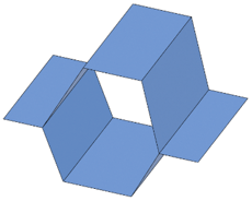
| Step 1: Create Concept geometry |
Step 2: Define FE properties and assign them to geometry |
Step 3: Generate mesh |