- On the FMU to the left in the figure below, drag from the stacked connector group.
A connection line appears and follows the cursor. 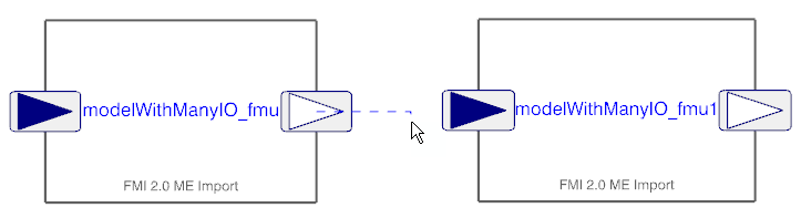
- Select the left stacked connector group on the second FMU.
The Connection dialog box appears. The dialog box shows the stacked connector groups in separate panes. Each pane lists the stacked connectors in that group. The connect statement at the bottom of the dialog box shows which connectors are selected from each group for the connection. -
From the left pane in the
Connection dialog box, select the connector to be connected.
The connector is displayed in the
first part of the connect statement.
-
From the right pane in the
Connection dialog box, click the connector to be connected to.
The connector is displayed in the
second part of the connect statement.
-
Click OK.
The connection is created. If you want to check the connection, you can: - Pause over the connection line. The tooltip shows the connection.
- Open the Modelica Editor. To see the connection in the connect equations, expand
 . For entering the Modelica Editor, see Displaying and Editing Modelica Text. . For entering the Modelica Editor, see Displaying and Editing Modelica Text.
- Optional: To rearrange the connection lines, use the following steps:
Rearranging connections is required if several connection lines are overlapping during connection. You can separate the connection lines by dragging the line points. - Click the connection line.
The last created connection line is selected.  - Drag the endpoint of the connection line to get more line points to work with.
- Drag the connection line points and drop them to separate them from other connection line points.
The following image shows an example after the rearranging of connections is done. 
-
Perform
Step 1 - Step 6 for all connections you want to rearrange.
Note:
You get no warning if you happen to connect to a connector already connected to. To see all connections, you must enter the Modelica text and expand the connect equations . For entering the Modelica Editor, see Displaying and Editing Modelica Text.
|
 . A connection line appears and follows the cursor.