Use Direct Connection
You can create a connection using direct connection, that is,
dragging from one connector to another. This is the default way to connect.
In this scenario, you connect a resistor to a capacitor. You also
create an intermediate port.
Before you begin:
To be able to create direct connections, make sure that the direct
connection mode is active, it is active by default. If it is not activated,
activate it by, from the
Diagram section of the
action bar,
clicking
Direct Connection
 . .
Notes:
- The command works in toggle mode.
- The command is actually a shortcut to the option
Use direct connection from
,
the
Editor tab.
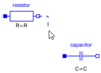
- Drag from the connector you want to connect.
A connection line appears and follows the cursor. - Optional:
You can perform the following actions when drawing the connection line:
- Click to create a way
point for the connection line. When you now drag in another direction, a
corner is created on the connection line.
- By default, corners on
the connection line are created as 90 degrees. To have any angle,
right-click and clear Right Angle Mode.
- To create a connector
on the connection line, right-click and select Create
Connector.
- To create a node on the
connection line, right-click and select Create
Node.
- To cancel the
connection, right-click and select Cancel
Connection.
-
Click the diagram layer to create a way point for the connection.
- Optional:
To create a connector on the connection line, do the following:
-
Right-click and select Create Connector.
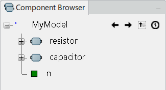
A new port ( n) is created. 
Note:
This port also appears in the Component
Browser:

-
Start a new connection from the new connector. See Step 1 above.
- Finish the connection by selecting the left connector of the capacitor.
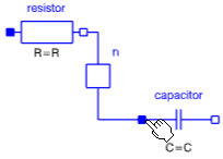
The connection is created. If you also have created the optional new
connector, you have:  If not, you have:

Use the Connection Starter
You can create a connection between two components using the
connection starter.
In this scenario, you connect a resistor to a capacitor. You also
create an intermediate port.
Before you begin: To be able to use
the connection starter, you must activate the option
Use the connection starter from
,
the
Editor tab. From this
tab, you can also define the shape and size of the connection starter in
general.
-
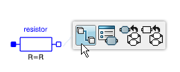
Pause the cursor over the connector you want to connect.
The following appears:
- A tooltip displaying
information about the connector.
- A gray area around
the connector, that is the connection starter.
-
Move the cursor just outside the connector, but still in the
gray area surrounding the connector.
 A new tooltip
Connection Starter appears.
-
Click or drag to start the connection.
A connection line appears and follows the cursor.
- Optional:
You can perform the following actions when drawing the
connection line:
- Click to
create a way point for the connection line. When you now drag in another
direction, a corner is created on the connection line.
- By default,
corners on the connection line are created as 90 degrees. To have any angle,
right-click and clear
Right Angle Mode.
- To create a
connector on the connection line, right-click and select
Create Connector.
- To create a
node on the connection line, right-click and select
Create Node.
- To cancel the
connection, right-click and select
Cancel Connection.
-
Click the diagram layer to create a way point for the
connection.
- Optional:
To create a connector on the connection line, do the following:
-
Right-click and select
Create Connector.
A new port ( n) is created.

Note:
This port also appears in the
Component Browser:

-
Start a new connection from the new connector. See Step 1 -
Step 3 above.
-
Finish the connection on the left connector of the capacitor in
any of the following ways:
- Pause over the
connector, and select its connection starter.
- Select
directly the connector.
The connection is created. If you also have created the
optional new connector, you have:
 If not, you have:

Use the Start Connection Command
You can create a connection between two components using the
connection starter.
This way to connect is always available.
In this scenario, you connect a resistor to a capacitor. You also
create an intermediate port.
-
From the
Behavior Authoring section of the
action bar,
click
Start Connection

-
Click the connector you want to connect.
-
Move the cursor.
A connection line appears and follows the cursor.
- Optional:
You can perform the following actions when drawing the connection
line:
- Click to create a
way point for the connection line. When you now drag in another direction, a
corner is created on the connection line.
- By default,
corners on the connection line are created as 90 degrees. To have any angle,
right-click and clear
Right Angle Mode.
- To create a
connector on the connection line, right-click and select
Create Connector.
- To create a node
on the connection line, right-click and select
Create Node.
- To cancel the
connection, right-click and select
Cancel Connection.
-
Click the diagram layer to create a way point for the connection.
- Optional:
To create a connector on the connection line, do the following:
-
Right-click and select
Create Connector.
A new port ( n) is created.

Note:
This port also appears in the
Component Browser:

-
Start a new connection from the new connector. See Step 1 -Step
3 above.
-
Finish the connection by selecting the left connector of the
capacitor.
The connection is created. If you also
have created the optional new connector, you have:
 If not, you have:

|
![]() .
.


