General Information
This contains some general information regarding the manufacturing features of an XML
model.
Manufacturing features: Burn Side Up/Opening/Attachment
Line/Reference Line/Positive Margin/Negative Margin/Edge Preparation/Roll Line.
The information about manufacturing features through XML provides, the Geometry, Text,
Graphic, and others.
Burn Side Up
This section provides information on the Burn Side Up.
- The Plane node is based on the Burn Side Up feature.
- The origin and direction of X and Y for Burn Side Up:
-
- This information provides the X and Y direction based on the 2 dimension plane.
- Most of the feature geometry projects to this 2D plane and then extracted.

Outer Contour
This section provides information on the Outer Contour.
Geometry Node
- Get all edges on the boundary of the plate such as line, arc, and curve.
- Extract geometric information.

Outer Contour - Line Case
This section provides information on the outer contour line case.
- Start and end points requirements for line:
-
- Get start and end points of line.
- Project all points to 2D plane.
- Add the information about point location projected to XML.
- XML Extraction.

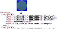
Outer Contour - Arc Case
This section provides information on the outer contour arc case.
- Start, middle, end, and center origin points and radius information is the requirements
for the line node in XML.
-
- Get all required parameter values.
- Project position values to the 2D plane and get information about projected point
location.
- Add the information about point location projected to XML Start and end points
required for the line.
- XML Extraction

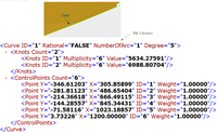
Outer Contour - Curves Case
This section provides information on the outer contour curves case.
- All curve lines except circles or arcs consider as Curves.
- Two tags Knots Count and Control Points
Count;
- Knots ID, Multiplicity, and value are requirements for Knots Count.
- X,Y point and weigh and weight are requirements for Control Points Count.
- Get all parameters;
- Get all parameter values.
- Project each control point to the 2D plane and get information about projected point
location on the 2D plane.
- Add each point information to XML Start, middle, end, and center origin points and
radius information are requirements for the line node in XML.
- XML Extraction.
Opening Feature
This section provides information on the opening features.
- Marked, Cut, Tabbed, Bridged, and Drilled types are available.
- Opening feature information provides information as Marking or Cutting to XML.
-
- Marking Element: Marked, Drilled.
- Cutting Element: Cut, Bridged, Tabbed.

Opening Feature - Marking Element
This section provides information on the opening features, marking
element.
Marked and drilled openings are provided as the Marking element in
XML.

Opening Feature - Drilled Opening
This section provides information on the opening features, drilled
opening.
Geometry Node: Gets all edges on boundary of opening contour such as
line, arc, and curve.
Opening Feature - Tapped Opening
This section provides information on the opening features, tapped
opening.
Geometry Node: Gets all edges on boundary of opening contour such as
line, arc, and curve.

Opening Feature - Cutting Element
This section provides information on the opening features, and cutting
element.
Cut and Bridged openings are provided as the Cutting element in XML.

Opening Feature - Cut Opening
This section provides information on the opening features, tapped
opening.
Geometry Node: Gets all edges on boundary of opening contour such as
line, arc, and curve.

Opening Feature - Bridged Opening
This section provides information on the opening features, bridged
opening.
Bridged Opening Tag;
- Get two domains of bridged opening.
- Get all edges on each domain such as line, arc, and curve.
- Generate two cutting nodes for one bridged opening.

Boundary Opening Feature
This section provides information on the boundary opening features.
- If the boundary opening feature is cut type, the boundary opening geometry applies to
the outer contour.
- There is no any geometry information in the cut opening tag. In other opening types, the
behavior is the same with the inner contour case.

Marking Line Features
This section provides information on marking line features.
Attachment Line, Reference Line, and Roll Line are Marking nodes.

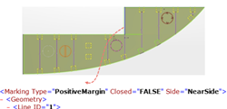
Positive Margin Features
This section provides information on margin features.
Positive Margin is provided as the Marking node.
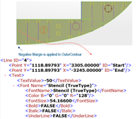
Negative Margin Features
This section provides information on negative margin features.
Negative Margin is not provided as Marking, text information is
provided only under the Outer Contour cutting node.
Edge Preparation Feature
This section provides information on edge preparation features.
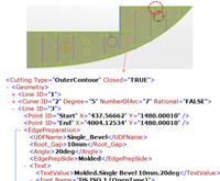
Edge Preparation feature is a part of the line under Outer Contour
and this provides the Angle, RootGap, and
user defined parameters.
Global Orientation
This section provides information about the global orientation.
Under U Dir, and V Dir node, provides text
and font nodes.

User-Defined Texts
This section provides information about the user-defined texts.

Text Node
This section provides information about the text node.
Drawing text in DPR is based on text and font properties, and is under any feature node, if
text exists.

Font Node
This section provides information about the font node.
Font node is under Text node in XML, and properties applies to text in DPR.

Graphic XML Node
This section provides information about the graphic XML node.
This provides graphic information for each feature, and not used in Act/Cut.

Roll Line Orientation
This section provides information about the plate/panel orientation and radius of the
roll line in the plate/panel fabrication sketch and in the XML file.
When viewing the marking face in the flattened plate/panel normally, that is, then the BSU
+Z direction points toward you. The plate/panel at the roll line forms toward you (that is,
toward the BSU +Z direction) or away (that is, opposite of the BSU +Z direction.)
When viewing the marking face normally, (that is, the BSU +Z direction points toward you)
the plate forming is toward you (that is, toward the BSU +Z direction.)

When viewing the marking face is normally (that is, the BSU +Z direction points toward
you.) The plate forming is away from you (that is, opposite of the BSU +Z direction.)

- If the plate/panel is formed toward you, that is, toward the BSU +Z direction when the
marking face is viewed normally, the orientation of the roll line is This
side.
- If the plate/panel is formed away from you, that is, opposite of the BSU +Z direction
when the marking face is viewed normally, the roll line orientation is Other
Side.
When the plate forming is away from you at the roll line when the marking face is viewed
normally, the orientation of the roll line isOther Side.

Roll line radius and orientation displays;
- Roll Line tab of Edit Features of formed plate/panel properties;
- Radius: Radius of curvature of the roll line
- Orientation: The orientation of the roll line
(This Side or Other Side).

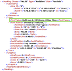
- Annotation text of the roll line feature contains the name of the roll line, radius,
and orientation of the roll line. Text = [Name of Roll line feature], [Radius],
[Orientation].

- Plate/Panel fabrication sketch contains the annotation text of the roll line,
RollLine.1, 2438mm, Other Side (1). This is the Near Side View.15, Scale 1:50.

- Plate XML in the text node of the roll line containing the radius and
orientation.
|


