Shrinkage Panel Compensation | ||
| ||

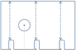
For example, in the above panel assembly, the panel shrinks in both transversal directions, because of the 12 welds present in the lateral direction. The panel also shrinks in the longitudinal direction, because of the 4 welds present in the longitudinal direction.
Each weld shrinks the panel by a certain value depending on various factors like material, thickness, cross section area of weld metal, and weld current. Therefore, the total shrinkage compensation depends on the number of welds present along the particular direction, transversal, or longitudinal. It also depends on the amount of shrinkage compensation required for each weld.
In addition, the opening contours do not deform because shrinkage. However, the position of the openings must move by the shrinkage amount required.
Complete this through the affinity feature for plates/panels, where you define the origin of the affinity and the shrinkage ratios along the required directions. However, this applies to individual features including outer contour, attachment lines, reference lines, opening contours. The shrinkage ratio needs to compute.
For example, when shrinkage compensation finishes for the panel above, the affinity applies to:
- the external contour of a plate or panel
- Marking lines, scale them with the contour.
- anchor points of all openings and slots, and move the openings and slots to the transformed anchor points
The result after applying the shrinkage compensation.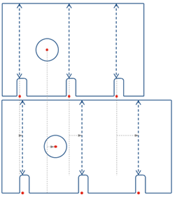
In this scenario, the U-axis and V-axis are displayed graphically in the auxiliary viewer when the Edit Features command is launched for the shrinkage compensation panel. By default, the axis displays at the BSU origin point. Select a point as the origin of the axis as per convenience. Shrinkage value defines for each impacting object for the U and V directions of the affinity axis. The shrinkage ratios in the U and V directions automatically compute from this value and applied on:
- The outer contour
- All marking lines (Reference line, Attachment line)
- COG of Openings and slots, and then the COG of the original contour moves to the transformed COG.
- COG of scallops, and then COG of scallops move to the transformed COG.

Specify the possible shrinkage values per impacting object in the data setup, Shrinkage Ratio Table and, Using Shrinkage Planning for Split Plate / Panel Compensation.