Using Shrinkage Planning for Split Plate / Panel Compensation | |||||
|
| ||||
-
From the Authoring section of the action bar, click Shrinkage Planning
 .
The Shrinkage Planning panel appears and lists the selected part. This creates a shrinkage IPM (In-Process Model) having shrinkage ratio 1 in both the U and V direction of the selected panel (split plate) / plate. U direction corresponds to the X of BSU and V direction corresponds to Y of BSU.
.
The Shrinkage Planning panel appears and lists the selected part. This creates a shrinkage IPM (In-Process Model) having shrinkage ratio 1 in both the U and V direction of the selected panel (split plate) / plate. U direction corresponds to the X of BSU and V direction corresponds to Y of BSU.
-
From the Authoring section of the action bar,
click Edit Features
 .
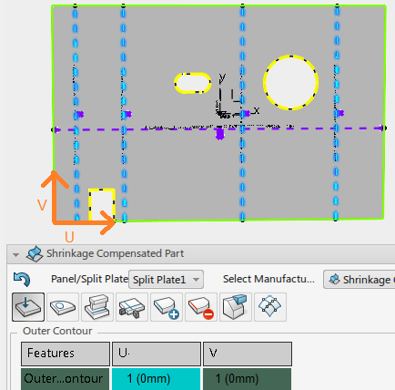
The Shrinkage Compensated Part panel appears to edit the shrinkage values.
.
The Shrinkage Compensated Part panel appears to edit the shrinkage values.
A graphical U and V direction Ratios displays at the origin of BSU, with U direction parallel to X of BSU and V direction parallel to Y of BSU. -
Click the Axis Origin window.
The origin location of this axis can shift by choosing the required origin point from the auxiliary point.

The total shrinkage ratio for the part depends on the number of impacting objects (attachment lines on the plate/panel). The system automatically computes the impacting objects in the U and V direction of the affinity axis.
The attachment lines perpendicular to the U direction are the impacting objects in the U direction. The attachment lines perpendicular to the V direction are the impacting objects in the V direction.
The cell under the U cell displays the shrinkage ratio applied and the shrinkage value impacting the object in brackets. For example, 1 (0mm) denotes the shrinkage ratio is 1 and the shrinkage value impacting the object is 0mm.
Clicking the cell under U, the impacting objects for U direction are highlighted in the auxiliary viewer.
When clicking the cell under V, the impacted objects for V direction is highlights.The cell under the V cell similarly displays the shrinkage ratio applied and the shrinkage value impacting the object in the brackets. For example, 1 (0mm) denotes the shrinkage ratio is 1 and the shrinkage value per impacting object is 0mm.
The impacting objects are edited with Edit Impacting objects.
-
Click Edit Impacting objects.
 A panel appears showing all the attachment lines impacting the U direction, V direction and the remaining, which do not impact U nor V.
You are provided with the Shrinkage Propagation option panel to decide profiles, along which direction they can be treated for shrinkage compensation. By default, the propagation option is turned off.
Based on the location of the reference axis and the propagation options selected the following are the use cases:
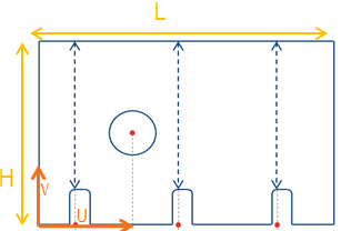
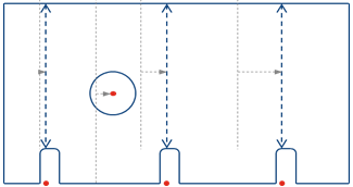
The shrinkage margin computation is explained with the data as shown in this image.

The profiles are P1, P2, P3, P4, P5.As an example, it is assumed that, for each stiffener welded to a plate / panel the shrinkage compensation to be added is of a value 0.1mm. The Shrinkage reference axis is at the bottom corner of the plate /panel.
- Shrinkage applied along U direction only and propagation
Along U direction option is turned
ON.

- Total Shrinkage added along U direction is equal to 0.2 mm since there are two impacting stiffeners, P4 and P5.
- Shrinkage values on Impacted Profiles are:
- P1 : 0 mm - since shrinkage of material because welding of P4 and P5 lie beyond Profile P1 with reference to U direction
- P2: 0.1 mm - Only 1 Profile, P4, is welded within the length of profile P2. Hence, the total impacted shrinkage value is 0.1 mm for profile P2.
- P3: 0.2 mm - Welding of both Profiles, P4 and P5, impact length of Profile P3. Hence the total shrinkage compensation added on Profile P3 is 0.2 mm.
- In this case, all the shrinkage compensations (Shrinkage margin) are added to the end of Profiles since shrinkage is applied on the plate along the positive U direction. There is no shrinkage compensation applied on the plate / profile along the negative U direction. Hence Start of Profile is not impacted.
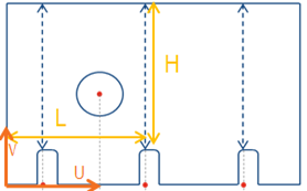
- Shrinkage applied along V direction only and propagation
Along V direction is turned
ON.

- Total Shrinkage added along V direction is equal to 0.3 mm since there are three impacting stiffeners namely P1, P2, and P3.
- Shrinkage values on Impacted Profiles are:
- P4 : 0.3 mm - Welding of Profiles, P1, P2, and P3, impact length of Profile P4. Hence the total shrinkage compensation added on Profile P4 is 0.3 mm.
- P5 : 0.3 mm - Welding of Profiles, P1, P2, and P3, impact length of Profile P5. Hence the total shrinkage compensation added on Profile P4 is 0.3 mm.
- In this case, all the shrinkage compensations (Shrinkage margin) are added to Start of Profiles since shrinkage is applied on the plate along the positive V direction. There is no shrinkage compensation applied on the plate / profile along the negative V direction. Hence End of Profile P4 and P5 is not impacted.
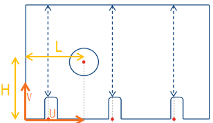
- Shrinkage applied along U and V
direction. Propagation Along Both direction is turned
ON.

- Total Shrinkage added along V direction is equal to 0.3 mm since there are three impacting stiffeners namely P1, P2, and P3.
- Total Shrinkage added along U direction is equal to 0.2 mm since there are two impacting stiffeners namely P4 and P5.
- Shrinkage propagation applied on each profile is as indicated in the above image. Computation is the same as explained in the examples above.
- Propagation option Along U direction selected
- In this case, Shrinkage compensation is applied to profiles P1, P2, and P3 only.
- Profile lengths of P4 and P5 are not impacted even if shrinkage is applied along V direction.
- User can choose this option if all Profiles along U direction, that is, ProfileP1, P2 and P3, are welded first.
- Propagation option Along V direction selected
- In this case, Shrinkage compensation is applied to profiles P4 and P5 only.
- Profile lengths of P1, P2, and P3 are not impacted even if shrinkage is applied along U direction.
- Use this option if all Profiles along V direction are welded first.
- Shrinkage applied along U direction only and propagation
Along U direction option is turned
ON.
-
Double-click the U or V cell and select
the appropriate shrinkage value for the U and
V directions.
Once the values are selected for the U and V directions, the system automatically computes the shrinkage ratios to be applied on the features.
- Shrinkage ratio for Outer Contour:
U-Ratio = (L + n1*s1)/L
Where n1= number of impacting objects for U direction.
S1= shrinkage value defined for U in the dialog.
V-Ratio = (H + n2*s2)/H
Where n2= number of impacting objects for V direction.
S2= shrinkage value defined for V in the dialog.
-
Shrinkage ratio for marking line:
U-Ratio = (L + n1*s1)/L
Where n1= the number of impacting objects for the U direction lying before the marking line up to the selected origin of the affinity.
S1= shrinkage value defined for U in the dialog.
V-Ratio = (H + n2*s2)/H
Where n2= the number of impacting objects for the V direction lying before the marking line up to the selected origin of the affinity.
S2= shrinkage value defined for V in the dialog.
-
Shrinkage ratio for Opening/Slot COG:
U-Ratio = (L + n1*s1)/L
Where n1= the number of impacting objects for the U direction lying before the opening extremity up to the selected origin of the affinity.
S1= shrinkage value defined for U in the dialog.
V-Ratio = (H + n2*s2)/H
Where n2= the number of impacting objects for the V direction lying before the opening extremity up to the selected origin of the affinity.
S2= shrinkage value defined for V in the dialog.
-
System computed shrinkage ratio is applied to (in a single step):
The external contour; All marking lines (Reference line, Attachment line); the COG of Openings and slots, and then the COG of the original contour moves to the transformed COG.
This shows the transformed outer contour, marking lines (attachment lines) and openings after applying the shrinkage ratios in the U and V directions.
- Shrinkage ratio for Outer Contour:


