Strategy Parameters | ||
| ||
![]()
General Parameters
- Tool Axis
The Tool Axis command in the Turning Operations dialog box is represented by an arrow when creating a part operation.
See Defining the Tool Axis
- Orientation
- Specifies the orientation of the groove to be machined as:
- Machining Direction
- Specifies the machining direction as:
- To head rough stock or From head rough stock for Internal orientation.
- To head rough stock or From head rough stockInternal for External orientation.
- To Spindle or From Spindle for Frontal orientation.
- Right of Groove or Left of Groove for Other orientation.
Note: If start and end limit mode defined in Geometry tab are in conflict with the machining direction, then these is reversed automatically. - Contouring for Outside Corners
-
Specifies the contouring of corners as:
- Angular
- Circular
Note: The geometry part profile is respected in this case. - Under Spindle Axis Machining
- This option allows you to request machining under the spindle
axis.Note: This option is activated when orientation is in Frontal mode.
- CUTCOM
- Specifies cutter
compensation so that the NC output
includes CUTCOM instructions in approach and retract paths for cutter
compensation. You can specify:
- On: CUTCOM/RIGHT instruction generated if tool is to the right of the tool path and CUTCOM/LEFT if tool is to the left of the tool path.
- Reverse: CUTCOM/RIGHT instruction generated if tool is to the left of the tool path and CUTCOM/LEFT if tool is to the right of the tool path.
See Cutter Compensation with Finish Turning Operations.
- Tool Compensation
- Select a tool
compensation number corresponding to the required tool
output point.
The usable compensation numbers are defined on the tool assembly linked to the machining operation.
By default, the output point corresponding to type P9 is used, if you do not select a tool compensation number.
- Change Output Point
- Select the Change Output Point check box to
automatically manage the change of output point. .
The two selections:
None: If the output point is consistent with the flank of the groove to be machined, the output point is changed when the other flank of the groove is machined. At the end of the Machining Operation, the output point is the same as it was at the start of the Machining Operation. See Tool Output Point Change. - Profile Output On Part
-
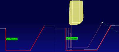
This computes a tool path is the result of Part Geometry and tooltip Coordinates. When Profile Output on Part option is selected, the tool path replay displays both tool paths. For example, tool path with respect to tool (p9) compensation point (orange color) and tool path related to profile output on part (white color).
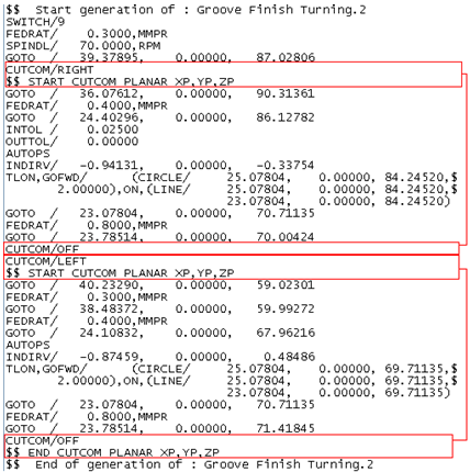
 Note: Profile Output on Part has a specific APT generation with clear start and end marks. Groove finishing MO tool paths haves the corresponding CUTCOM call with proper end statements.
Most of the standard CNC machine controls have a feature that enables the CNC programmer to apply an offset command to compensate the cutter nose radius. Here the part is programmed by its contour as per drawing dimensions and the control system does the required calculations and adjustments automatically. The figures below shows how the controller behaves with and without CUTCOM.
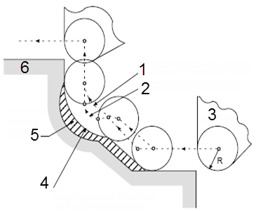
- Tool path without compensation
- Tool path with compensation
- Tool Nose
- Shape processed without tool nose radius compensation
- Insufficient depth of cutting
- Workpiece
Without tool nose radius compensation, the imaginary tool nose path is the same as the programed path.
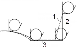
- Imaginary tool nose path
- Start-up
- Programmed path
Without tool nose radius compensation, the imaginary tool nose path is the same as the programmed path.
- Imaginary tool nose path
- Start-up
- Programmed path
Here a Part programmed is nothing but valid tool path with respect to Profile output on part. This allows you to control the pertinence of the tool path position related to the part profile geometry using the CNC machine controller and CUTCOM option. It is a convenient way to have a clear visualization of the tool path.
With a Material Removal/Machine Simulation: Only the cutter center tool path is taken in to account during tool path replay. Tool path replay is not based on the tool path related to profile output on part.
Limitations: The controller has to take care moving from one CUTCOM to another, as this alters the CUTCOM side, and there is no change from existing behavior. Only the cutter center tool path is taken into account and simulation is done based on this.
Machining Parameters
- Insert-holder constraints
- Specifies insert-holder constraints as:
- Ignore
- Apply
The following attributes (located on the Insert-holder's Technology tab) may influence machining: See Creating and Editing Milling, Drilling, and Probing Tools
- Gouging angle
- Trailing angle
- Leading angle
- Maximum recessing depth
- Maximum cutting depth
- Maximum boring depth
These attributes take tooling accessibility into account and may reduce the machined area.
Note: Use the Insert-Holder Constraints option to either ignore or apply these attributes. You can replay the Machining Operation to verify the influence of these attributes on the generated tool path. - First flank lead-in
- Defines the type of
lead-in at lead-in feedrate on the first flank of the
groove.
You can specify:
- Linear: Lead-in up to the point where first flank machining starts is defined by the first lead-in distance and first lead-in angle parameters.
- Circular: Lead-in is circular and tangent to the point where first flank machining starts. It is defined by the first lead-in radius and first lead-in angle parameters.
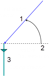
The first lead-in angle is defined with respect to the normal to the cutting direction. The figure below shows the effect of a positive first lead-in angle for external machining (1 - First lead-in vector, 2 - Positive first lead-in angle, 3 - Cutting direction).
- Last flank lead-in
- Defines the type of lead-in at lead-in feedrate on the last flank of the
groove.
You can specify:
- Linear: Lead-in up to the point where last flank machining starts is defined by the last lead-in distance and last lead-in angle parameters.
- Circular: Lead-in is circular and tangent to the point where last flank machining starts. It is defined by the last lead-in radius and last lead-in angle parameters.
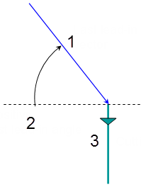
The last lead-in angle is defined with respect to the normal to the cutting direction. The figure below shows the effect of a positive last lead-in angle for external machining(1 - Last lead-in vector, 2 - Positive last lead-in angle, 3 - Cutting direction).
- Other Flank Lead-in
- Defines the type of lead-in required to machine flanks other than the first
and last flanks, for a groove that has multiple recesses. You can specify:
- Linear
- Circular
- Lift-off Type
- Defines the type of lift-off from the groove at lift-off feedrate.
You can specify:
- Lift-off Distance: When lift-off type is Linear.
- Lift-off Angle: When lift-off type is Linear or Circular.
- Lift-off Radius: When lift-off type is Circular.
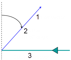
The lift-off angle is defined with respect to the normal to the cutting direction. The figure below shows the effect of a positive lift-off angle for external machining(1 - Lift-off vector, 2 - Positive lift-off angle, 3 - Cutting direction).
- Other Flank Lead-in Distance
- Specifies other flanks of the groove when other flank lead-in type is Linear.
- Other Flank Lead-in Angle
- Specifies other flanks of the groove when other flank lead-in type is
Linear or
Circular.Note: The Other Flank Lead-in Angle is defined with respect to the cutting direction.
- Other Flank Lead-in Radius
- Specifies other flanks of the groove when other flank lead-in type is
Circular. Note: The Other Flank Lead-in Radius is defined with respect to the cutting direction.
- Machining Tolerance
- Specifies the maximum allowed distance between the theoretical and computed tool path.
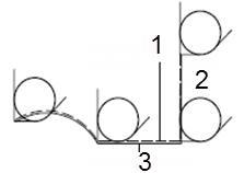
- Clearance (1)
- This value defines the clearance to be applied to the next flank after the
first machined flank. The bottom of the groove (2) is machined up to the
position defined by this clearance value.Note: For machining operations with Orientation specified as Other, the clearance value is not applied for grooves with an inclined groove bottom.
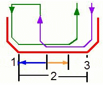
- Overlap (3)
- This value defines the amount of machining overlap at the bottom of the groove.Note: The sum of the Clearance and the Overlap must be less than or equal to the groove bottom width. Otherwise a warning message is issued. The groove bottom width is the horizontal bottom of the groove, or the length of the bottom element of the groove where there is no vertical component. For a circular groove, the groove bottom width is zero.
Corner Processing Parameters
- Entry, Exit, and Other corners
- Entry Corner means the first corner on the part
profile in the specified machining direction. Exit
Corner means the last corner on the part profile in the
specified machining direction. Corner processing is proposed for
Entry, Exit , and
Other corners. . The
Entry/Exit corners are determined according to
the specified machining direction and not by the tool motion.
You can specify:
- None: No corners are to be machined along the profile.
- Chamfer: Only 90 degree corners of the profile are chamfered.
- Rounded: All corners of the profile are rounded.
The following options availability depends on the following conditions:
- Chamfer Length: If Other corner processing mode is Chamfer.
- Corner Radius: If Other corner processing mode is Rounded.
- Entry Corner Chamfer Length: On first flank of groove when Entry corner processing mode is Chamfer.
- Entry Corner Radius: On first flank of groove when Entry corner processing mode is Corner.
- Entry Corner Angle: On first flank of groove when Entry corner processing mode is Corner.
- Exit Corner Chamfer Length: On last flank of groove when Exit cornerprocessing mode is Chamfer.
- Exit Corner Radius: On last flank of groove when Exit corner processing mode is Corner.
- Exit Corner Angle: On last flank of groove when Exit corner processing mode is Corner.