Previewing Spindle Way of Rotation during Replay and Simulation | ||
| ||
-
Select
Me
 > Preferences > App Preferences > Simulation > Machining
and select the display color of the Spindle Rotation
Arrow and of the Spindle Rotation Arrow Head from the
lists.
The spindle way of rotation is not available by hovering the mouse but is available in the context menu Activate Spindle Direction Display.
> Preferences > App Preferences > Simulation > Machining
and select the display color of the Spindle Rotation
Arrow and of the Spindle Rotation Arrow Head from the
lists.
The spindle way of rotation is not available by hovering the mouse but is available in the context menu Activate Spindle Direction Display. -
Right-click the spindle in PPR Context and select .
By default,
The spindle direction is displayed as a 3D arrow in the 3DEXPERIENCE platform.
- The arrow is positioned on the plane perpendicular to the spindle axis.
- The diameter of the arrow is determined by the maximum size of the product to machine.
-
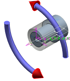
Select Rough Turning operation and
Drilling operation having fixed tool and click Simulate or Display.
Spindle rotation is shown for Turning operation and Axial operation with fixed tool. The below image shows spindle way of rotation during Simulate or Display.
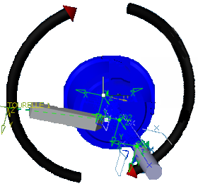
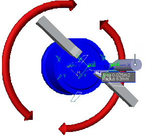
If a spindle is involved simultaneously in more than one activity with different ways of rotations, the spindle arrow is displayed in red color with two arrow heads indicating both clockwise and counter clock wise directions as shown in the image below.