Create a Longitudinal Rough Turning Operation
You can create a Longitudinal Rough Turning operation in the Manufacturing Program.
-
Activate the Manufacturing Program and click Rough Turning
 .
.A Rough Turning entity is added to the Manufacturing Program.
The Rough Turning dialog box appears directly at the Geometry tab
 .
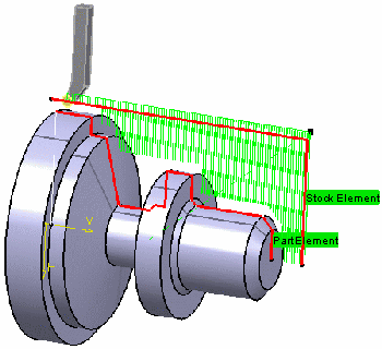
Note: Geometry tab includes a sensitive area to help you specify the geometry to be machined. The part and rough stock are colored red indicating that this geometry is requiredm. All other geometry is optional.
.
Note: Geometry tab includes a sensitive area to help you specify the geometry to be machined. The part and rough stock are colored red indicating that this geometry is requiredm. All other geometry is optional. - While still in the Geometry tab:
- Right-clicking on the red area helps you specify the geometry to be machined by curve or by face as an example in the context menu.
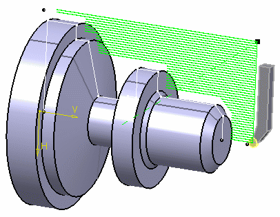
- Click the red part area in the Geometry tab and then select the
required part profile in the work area.
See Selecting Edges and Faces to Define Geometry and Selecting Faces of a Part in a Turning Operation.
The Automatic Link Type option
 allows you to select a first element and then
the element to navigate to in order to complete the profile selection.
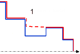
The Axial/Radial (1) and Radial/Axial (2) Linking options are also useful for
profile selection.
allows you to select a first element and then
the element to navigate to in order to complete the profile selection.
The Axial/Radial (1) and Radial/Axial (2) Linking options are also useful for
profile selection. 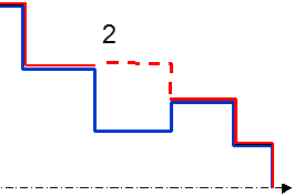
Once selected, the part area changes color to green indicating that this geometry is now defined.
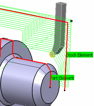
- Click the red rough stock area in the Geometry tab and then select the required
rough stock profile in the work area. Once selected, the rough stock area changes color to green indicating that this geometry is now defined.

- Right-click the geometry to be assigned the local value,
and select the Add Local Information context menu command.A dialog box appears allowing you to assign the required local values. In addition to the global offsets that you can assign to the part profile, you can also add local offset values.
Other context menu commands are available for managing local information. For more information, see Managing Local Information.
- Set Part Offset to 5mm.
- Select the Strategy tab
 .
.- Specify the machining strategy parameters.
- Roughing mode: Longitudinal
- Orientation: External
- Location: Front
- Double-click Max depth of cut Set this value to 2.5mm in the Edit Parameter dialog box and click OK.
- Define other parameters in the Option and User Parameters tab.
- Specify the machining strategy parameters.
- Go to the Tool tab
 to select a tool.
 - Select the Feeds and Speeds
tab
 to specify the feedrates and spindle speeds for the Machining Operation.
 - Select the Macros tab
 to specify the Machining Operation transition paths.For more information, see Defining Macros on Turning Operations.
 -
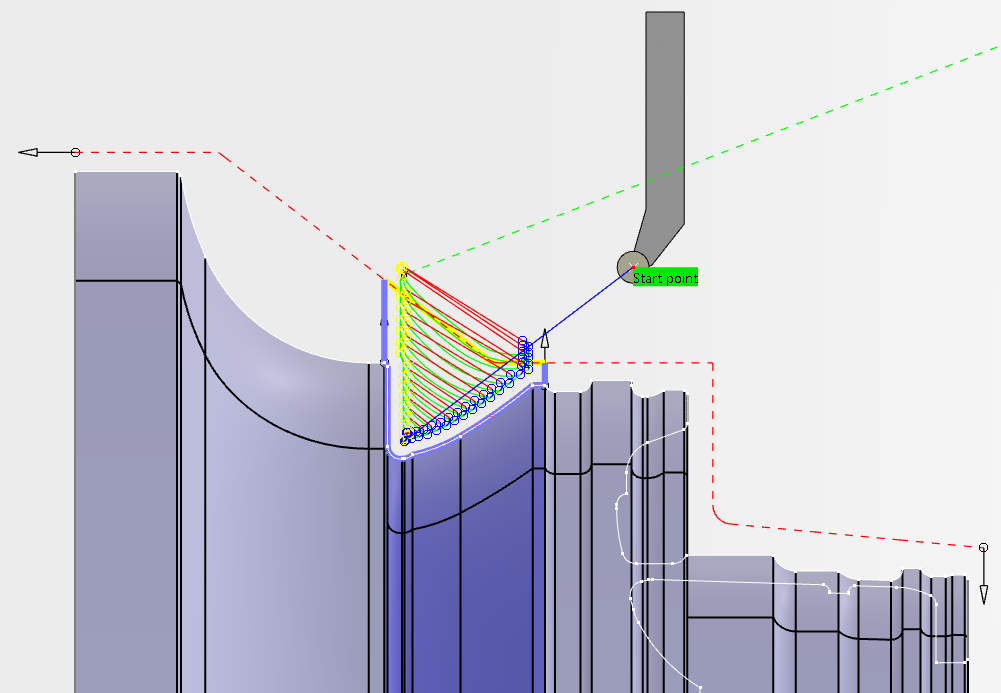
Click Simulate or Display to check the validity of the Machining Operation.
The toolpath is computed.
- The tool path is computed.
- A progress indicator is displayed.
- You can cancel the tool path computation at any moment before 100% completion.
 to specify the required transition paths.