Strategy Parameters | ||
| ||

Strategy
- Tool Axis
-
The Tool Axis command in the Turning Operations dialog box is represented by an arrow when creating a part operation.
See Defining the Tool Axis
- Max Depth of Cut
- Specifies the maximum distance between passes.
- Axial and Radial Depth of Cut
- Specifies the maximum axial and radial distances between passes for Parallel Contour mode.
- Roughing Mode
- Specifies the roughing mode.
You can specify:
- Longitudinal
- Face
- Parallel Contour
- Concentric
- Location
- Specifies the location.
It determines the way the program closes the area to machine using radial, axial, axial-radial, or radial-axial relimitation. The following machining locations are proposed:
- 1 > Front: the part is machined toward the head rough stock.
- 2 > Back: the part is machined from the head rough stock.
- Orientation
- Specifies the orientation.
It determines the way the program closes the area to machine using radial, axial, axial-radial, or radial-axial relimitation. The selected orientation defines the type of geometric relimitation to be done between the rough stock and part geometry to determine the area to machine. The following Orientations are proposed:
- Internal
- External
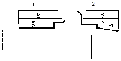
- Frontal: This is available only with Face and Parallel Contour Roughing Mode.
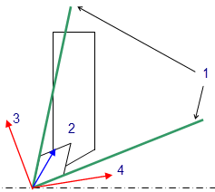
Selected part and rough stock profiles do not need to be joined (see the following figures).
1 is Part Profile
2 is rough stock Profile
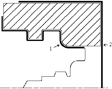
1 is Part Profile
2 is rough stock Profile
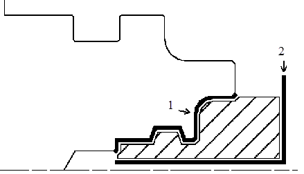
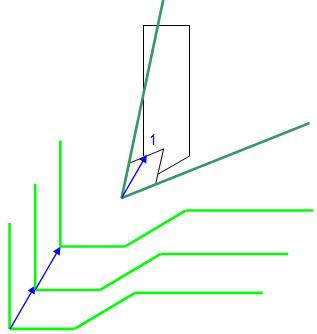
In Frontal machining, the minimum and maximum diameters of the area to machine are determined by the rough stock profile dimensions.
For example, in the following figure the area to machine is relimited by the spindle axis because the rough stock profile is also relimited by the spindle axis.
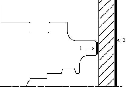
1 is Part Profile
2 is rough stock Profile
- Machining Direction
- Specifies the machining direction.
You can specify:
- Part Contouring
- Specifies a contouring type for Longitudinal and
Face roughing mode to clear the part profile by
means of the following settings:
- No: no contouring
- Each path: profile following at each roughing pass.
- Last path only: profile following at last roughing pass only.
- Recess Machining
- Select this check box, if you require recess
machining.
This check box is available if Part Contouring is Each path or Last path only. When recess machining is active in Parallel Contour roughing mode then Axial and Radial Depth of Cut must have suitable values to ensure a collision free tool path.
Recommendations for collision free Recess Machining in Parallel Contour roughing mode. Machining in Parallel Contour Rough turning is done by means of successive offsets of the tool path: the offset depends on the axial and radial depth of cut values. The following recommendations describe how to set the axial and radial depth of cuts to ensure a collision free tool path.
-
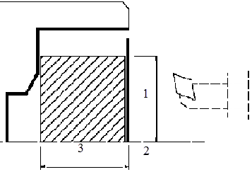
Parallel Contour Principle: The parallel contours of the Tool path are obtained by first shifting the last pass then shifting each successive pass depending on the axial and radial depth of cut values.

Then the passes are relimited taking into account the rough stock definition.1 - Shift between each pass
2 - Radial depth of cut
3 - Axial depth of cut
-
Correct Combination of Axial and Radial dDepth of Cuts: Compared with the left and right angles on the insert, the axial and radial depth of cut values define a shift direction that must be compatible with the insert.
The shift direction must be inside the limit angles defined on the tool insert otherwise a collision may occur. In collision cases, the collision is on the first pass, not on the last passes of the tool path.1 - Angles related to tool insert
2 - Compatible shift
3 - Incompatible shift
4 - Incompatible shift
-
Example of a Correct Combination:
1 - Compatible shift
-
Example of an Incorrect Combination (Right of Tool):

The parallel contour Tool path is in collision because the shift does not respect the tool insert angle on the right side.1 - Incompatible shift
-
- Under Spindle Axis Machining
- Select this check box to request machining under the spindle axis.
This is available with:
- Face roughing mode and Internal/External/Frontal orientation.
- Parallel Contour roughing mode and Frontal orientation.
- Tool Compensation
- Select a tool compensation number corresponding to
the required tool output point.
The usable compensation numbers are defined on the tool assembly linked to the Machining Operation.
By default, the output point corresponding to type P9 is used, if you do not select a tool compensation number.
- Change Output
- Select the Change Output Point check box to
automatically manage the change of output point. .
If the output point is consistent with the flank of the recess to be machined, the output point is changed when the other flank of the recess is machined.
At the end of the Machining Operation, the output point is the same as it was at the start of the Machining Operation. See Tool Output Point Change.
Information Specific to Concentric Tool Path Style
- Concentric Tool Path Style
- Builds a safe-cutting trajectory by controlling the engagement of the tool.
The trajectory created by the Concentric strategy adapts itself dynamically to ensure a safe cutting at nominal speed. The engagement of the tool is controlled to never exceed a maximum value, even in corner areas.
The strategy is particularly recommended for hard-material milling. In this type of material (for example titanium, stainless steel, ceramic...), the tool needs to be protected. Other tool path styles -based on a constant distance between passes- are not appropriate because the tool load will increase significantly when milling the inside of a radius. whereas the engagement is equal to the stepover when milling in a straight line. The Concentric strategy controls the tool load by modifying, for each motion, the distance between passes. As a result, the tool lifetime is increased and the machining time is optimized.
- Movement
-
- When Movement is set to One-Way, the tool path uses the selected cutting direction.
- When Movement is set to Zig-Zag, the tool path is optimized using both cutting directions (Climb and Conventional). The selected cutting mode is the main direction. Modifying it could change the trajectory.
- Reverse pass (radial %)
- Reverse pass (radial %) lets your define the reverse radial engagement when milling in the reverse direction, that is the direction not selected as the Direction of cut. The value is a percentage of the main radial engagement. A value equal to 100% keeps the same engagement for the main and the reverse directions.
- Contouring Pass and Contouring Ratio
- Available when the tool path style is set to Concentric. The Contouring Pass parameter lets you allow a final machining pass around the exterior of the trajectory for removing scallops. Contouring Ratio lets you adjust the position of the final contouring pass for removing scallops. This is done by entering a percentage of the tool diameter (0 to 50).
Options
- Lead-in Distance and Lead-in Angle
- Specifies the lead-in vector at the start of each pass with respect to the
normal to the cutting direction.
Lead-in distance takes the rough stock profile and rough stock clearance into account. The tool is in RAPID mode before this distance.
If no lead-in angle is requested, the lead-in path is normal to the cutting direction. For Longitudinal and Face roughing mode the lead-in angle is applied as follows:
- no angle applied to lead-in path
- lead-in angle applied to each path
- lead-in angle applied to last path only.
For Parallel Contour roughing mode, the lead-in angle is applied to each path.
- Distance before plunge and Angle before plunge
- Specifies the plunge vector before each new pass with respect to the cutting direction for Longitudinal and Face roughing mode.
- Attack Distance
- Specifies the attack distance with respect to the cutting direction and takes the rough stock profile and rough stock clearance into account.
- Lift-off Distance and Lift-off Angle
- Specifies the lift-off vector at the end of each pass with respect to the
cutting direction. and
For Longitudinal and Face roughing mode, lift-off occurs as follows:
- At the end of each pass, when Part Contouring Type is set to None or Last path only.
- At the end of the last pass of the Machining Operation, when the Part Contouring Type is set to Each path. This prevents the tool from damaging the part when returning to the end point in RAPID mode.
- At the end of each pass that ends on the rough stock profile.
For Parallel Contour roughing mode, lift-off occurs when the end of the pass has already been machined by a previous pass.
- Leading and Trailing Safety Angles
- The insert geometry is taken into account to avoid collision by reducing the
maximum slope on which the tool can machine. The Leading Safety
Angle and Trailing Safety Angle
allows you to further reduce the area to machine. The Trailing
Safety Angle is used only when Recess
Machining is set.
Leading and trailing angles can also be defined on the insert-holder to define the maximum slope on which machining is done. In this case and if the Insert-Holder Constraints setting is applied, the angles that reduce the slope the most is taken into account.
- Insert-Holder Constraints
- Specifies insert-holder constraints as:
- Ignore
- Apply
The following attributes (located on the Insert-holder's Technology tab) may influence machining: See Creating and Editing Milling, Drilling, and Probing Tools:
- Gouging angle
- Trailing angle
- Leading angle
- Max Recessing Depth
- Maximum Cutting Depth
- Maximum Boring Depth
These attributes take tooling accessibility into account and may reduce the machined area. However, you can use the Insert-Holder Constraints option to either ignore or apply these tooling attributes. You can replay the operation to verify the influence of these attributes on the generated tool path.
The Insert-Holder Constraints setting does not influence the Leading and Trailing Safety Angles.
- Minimum Machining Radius
- Specifies the minimum machining radius.
This option is available when Orientation is External.
- Leading Angle (Defined on Tool)
- Minimum Machining Radius
- Part Profile
- Leading Angle
- Spindle Axis
- Maximum Machining Radius
- Specifies the maximum internal machining radius.
This option is available with Face roughing mode, Internal/Frontal orientation, and From Spindle machining direction.
Note: Maximum boring depth is defined on the tool.
- Axial Limit for Chuck Jaws
- Specifies the axial limits for external or frontal
machining.
Offset is defined from the machining axis system.
- Machining Tolerance
- Specifies the maximum allowed distance between the theoretical and computed tool path.
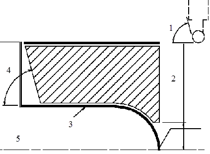
External Longitudinal Rough Turning
In the figure above, the tool motion is as follows:
- approach in RAPID mode
- lead-in at the first recess pass and plunge approach for other passes
- plunge at plunge feedrate
- machine at machining feedrate
- contouring at contouring feedrate
- lift-off at last recess pass at lift-off feedrate.
User Parameters
Balance Turning Parameters
- Sibling Operation
- Displays the name of created sibling Machining Operation.
- Sibling Corrector
- Specifies all the available tool compensations on the sibling tool.
Follow Turning Parameters
- Sibling Operation
- Displays the name of created sibling Machining Operation.
- Delay
- Specifies the delay (in linear unit) to start the secondary passes.
- Treat Odd Path
- Specifies strategy for the odd path. You can specify:
- Alone at the Start: Odd pass corresponding to the primary is always the first pass.
- Alone at the End: Odd pass corresponding to the primary is the last pass.
- End Point
- Specifies synchronization end point. You can specify:
- None: No synchronization at the end of passes.
- End Of Lift Off: Synchronization at the end of Lift Off of both Machining Operations.
- Sibling Corrector
- Specifies all the available tool compensations on the sibling tool.