Axis Systems | ||
| ||
Part Axis System
You can edit the Part Axis System (PAS) by clicking
![]() in the Spindle tab of the Generic Machine dialog box. The dialog box appears with the Axis Name: Part Axis (Main Spindle)
in the Spindle tab of the Generic Machine dialog box. The dialog box appears with the Axis Name: Part Axis (Main Spindle)
By default, the Reference Machining Axis System
![]() defined on the Generic Machine dialog box is assigned to the main spindle.
defined on the Generic Machine dialog box is assigned to the main spindle.
See Assign a Reference Machining Axis System
When same spindle is used in more than one Generic Machine in a CATProcess, then setting PAS of the spindle in one Generic Machine changes the PAS of the same spindle used in other Generic Machine. This in-turn changes the tool orientation in Generic Machine (say PO.1), if the new PAS set in another Generic Machine(say PO.2) is different from PAS already defined in first Generic Machine (PO.1).
For turning operations:
- The main spindle PAS is the reference for tool compensation computation. Other spindles and turrets have no influence.
- Part orientation is determined by the PAS of the selected spindle. Spindle axis must be defined from the chuck to the front of the Part. This is used for part orientation and location parameters.
For NC data output, a Machining Axis System change must be inserted in the program when changing spindle.
Turning Tool Axis System
Turning Tool Axis System defines the turret plane, which allows realistic representation for:
- Tool positioning
- Tool path visualization
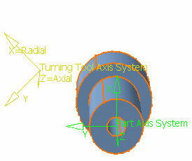
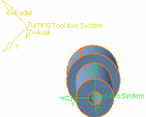
The images below illustrate for a given tool (Setup angle = 0deg / Radial axis X) the behavior when moving (Cut/Paste) an operation from Turret.1 to Turret.2.


Note that milling and drilling tools are positioned according to the tool axis defined at operation level. This offers following advantages:
- Reuse same tool definition in several turrets
- Allows off-line NCProgramming (no tool gauge required).
You can edit the Turning Tool Axis System by clicking
![]() in the Turret tab of the Generic Machine dialog box. The following dialog box:
in the Turret tab of the Generic Machine dialog box. The following dialog box:
- Turret Plane Definition: Axial and Radial axis
- The Axial and Radial axis of this axis system define the working plane
of the turret for turning operations. Tool path, replay, and time based
replay are represented in this plane.
This axis system is any axis system. However, the working plane must contain the spindle axis that the turret works on.
- Incline of Turret Plane: Angle
- Defines the incline of Turning Tool Axis system, through
its radial direction. The incline of the Turret Plane is with respect to
the ZX plane of the first spindle (that is, the Setup axis system). The angle gives an incline measured from the radial direction of the
main spindle PAS.

When the Turning Tool Axis system is rotated through the spindle axis of the main spindle PAS by 45 degree. The distance between the origin of the Turning Tool Axis system and the spindle axis of the main spindle PAS is unchanged.

The Turret Plane Definition, the Axial axis is Z and the Radial axis is X. The incline of the Turret Plane Angle is 45 deg and the Shift Origin of Turning Tool Axis System, Axial shift and Radial shift is 0mm.
The angle is an absolute angular position measured from the radial direction of the main spindle PAS (it is not a relative angle from the previous position).
When looking along the spindle axis of the main spindle PAS, the angle is positive in the counter-clockwise direction and negative in the clockwise direction.
Note: The Angle field is reset to 0, even if the current absolute position of the Turning Tool Axis system is not 0. - Shift Origin of Turning Tool Axis System: Axial and Radial Shift
- This parameter shifts the origin of the Turning Tool Axis system , through
its radial and axial directions.
The position of the origin of the axis
system is with relative to the origin of the first spindle (that is, the origin
of the Setup axis system).
This shift is done in the turret plane defined by the radial and axial directions of the Turning Tool Axis system .
Radial shift: gives a shift measured from the origin of the main spindle PAS in the radial direction of Turning Tool Axis system .
The radial shift must not be less than 0. To shift a turret from above to below the spindle, the incline angle must be used.

The Turret Plane Definition, the Axial axis is Z and the Radial axis is X. The incline of the Turret Plane Angle is 45 deg and the Shift Origin of TURNING Tool Axis System, Axial shift 100mm and Radial shift is 0mm.
Axial shift: Gives a shift measured from the origin of the main spindle PAS in the axial direction of Turning Tool Axis system .
The shift is an absolute position measured from the origin of the main spindle PAS (it is not a relative position from the previous position).
Note: Radial and axial shift fields are reset to 0, even if the current absolute position of the Turning Tool Axis system is not 0.