Create and Edit a Part Operation
You can access and create a Part Operation in the Activities Process Tree.
-
From
any product or 3D part:
-
Select a machining app then the Programming section.
A PPR Context with an empty Manufacturing
Cell is created with a Activities Process
Tree.
-
Create a generic machine or assign a
machine from the database.
As soon as a
machine is assigned to the Manufacturing
Cell, a Part Operation and a Manufacturing Program are created in the Activities Process
Tree.
-
Alternatively, open an existing
Machining Process or PPR Context.
By default, the Activities Process
Tree is available.
-
Select a machining
app
then the
Programming
section.
An empty
Manufacturing
Cell is created with an
Activities Process
Tree.
-
Create a generic machine or assign a
machine from the database.
As soon as a
machine is assigned to the
Manufacturing
Cell,
a
Part Operation
and a
Manufacturing Program
are created in the
Activities Process
Tree.
-
Alternatively, open an existing
Machining Process
or
PPR Context.
By default, the
Activities Process
Tree
is available.
-
If you need to add a Part Operation, click Part Operation
 . .
-
Double-click the Part Operation in the Activities Process Tree.
The dialog box to edit a Part Operation varies depending on the type of the machine.
- When the assigned machine is a milling machine, the Part Operation is:

- When the assigned machine is a mill turn machine, the Part Operation is:
- When the assigned machine is a wire EDM machine, the Part Operation is:
- Optional:
Click Comment
 to edit
the Part Operation Name and assign Comments to the Part Operation. to edit
the Part Operation Name and assign Comments to the Part Operation.
- Optional:
Edit the Setup
Options, and Transition Path tabs.
-
Optional: Edit the Air Cut Optimization
parameter.
- If activated: Removes cutting motion when the tool does not remove
any material, reducing machining time.
- If deactivated: Keeps cutting motion when the tool does not remove
any material, reducing computation time.
-
Click Analyze
 to open the Geometry Analyzer dialog box containing the
selected geometry points.
to open the Geometry Analyzer dialog box containing the
selected geometry points.
-
Click Reset all selections
 to reset all geometry selections in the 3DEXPERIENCE platform.
-
Click Define Feature to Recognize
 to select the faces of the feature to recognize for geometric form reuse. to select the faces of the feature to recognize for geometric form reuse.
Note:
If the part contains several geometric forms, you must define a setup
and a new NC assembly for each form on the part.
-
Click Show/Hide the offset
 to show/hide the offsets in 3DEXPERIENCE platform.
Assign a Reference Machining Axis System
You can assign a reference machining axis system to the Part Operation.
-
Click Reference Machining
Axis System
 . .
The Machining Axis System dialog box is
displayed.
-
See Inserting Machining Axis Changes.
Notes:
- Output coordinates are expressed in the reference machining axis system.
- If a local machining axis system is inserted in the Manufacturing Program, coordinates are expressed in the local axis system.
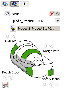
Define the Setup of the Part Operation
You can define the geometry of the Setup Assembly, the Design, the Stock,
Check elements and Safety planes from the Setup
tab.
Note:
Sketches are not supported to define design parts, stocks, or fixtures.
-
Go to the
Setup
tab
 . .
-
Assign
an existing setup assembly to the Part Operation.
-
Click Setup
Assembly
 to associate an existing setup assembly to
the Part Operation. to associate an existing setup assembly to
the Part Operation.
Note:
The setup assembly can be linked to only one setup position.
To select the same setup assembly, create a new instance under
the manufacturing cell using the Insert Setup Assembly
command or copying/pasting an existing instance.
The icon turns to  .
-
If required, click to remove the currently associated setup assembly.
The icon turns back to .
Note:
When replacing the Product or the Part, a warning message is displayed
if points have been created in the machining program . For example: When
defining the order of the pocket in a roughing operation, delimiting the
curve guide in tube machining, or defining the point to probe in a
multi-point probing operation. You can:
- Delete these points: The operations associated to these
points are incomplete and select new points again
- Keep these points: The new product/part of the part operation is
identical.
-
Click Design Part
then select the required geometry.
Recommendation:
You should define a solid as a part, and not
only surfaces.
The geometry of the design part is associated to the Part Operation. This is useful for material removal simulations.
-
Click
stock then select the required geometry.
A rough stock is associated to the Part Operation. This is useful for some Surface Machining Operations and also for material removal simulations.
-
Click
Fixtures then select the required geometry.
Fixtures are associated to the Part Operation. This is useful when you want to do material removal simulations.
-
Click Safety
Plane then select the required plane.
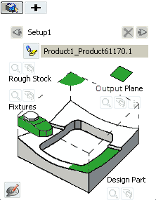
This plane is associated to the Part Operation, as its global safety plane. Note:
For wire EDM
operations, this parameter is replaced by the Output
Plane. This plane defines the height of the tool path on
the Z-axis.
- Optional:
Specify a feeds and speeds configuration to filter the search results of
cutting resources when launched from Search from
Session, Search from Catalog, or
Search from Database in the operation panel.
Note:
The lists displays what is defined under
.
The values are undefined by default, that is, no filter is applied to the
search results based on the feeds and speeds configuration.
If at least one value is defined, resources that have a feeds and speeds
configuration that matches the value specified on setup are included in
the search results. Conversely, resources without a feeds and speeds
configuration are excluded from the search results.
-
Click
+ to add a Setup.
A Setup
tab is added.
-
Click the left or right arrow to modify the order of the existing setups.
-
Click the red cross to delete an existing setup.
-
Right-click then Reference Machining Axis
System
on Part Operation
Setup
tab:
-
Click Table Center
Setup and modify the reference positions.
Setup delta X 4.00 mm, SetUp delta Y 0.00mm, SetUp delta 0.00mm.
-
Click OK.
Edit the Options of the Part Operation
You can edit several options of the Part Operation from the Option tab.
-
Go to
the Option tab
 . .
Only the relevant options are selectable:
Tool Path points
based on the turret axis system, and Collision
Checking, On geometries, Collisions check in on design part.
-
In General:
-
Define the value of the
Stocks Accuracy.
The Stock Accuracy is the tolerance used to
compute tessellations for material removal simulations. By
default, The Stock Accuracy is set to 0.2
mm.
-
For wire EDM operations, define the value of the Machine
Upper Head Height.
The Machine Upper Head Height defines the
output of the upper guide height, which is used by the
post-processor to compute U and V machine values.
-
Click Undo
 to revert to the default value. to revert to the default value.
-
Select the required check boxes:
- Use
Spindle Axis System defined in the Machining
Operation: When selected, computes the
tooltip points based on the spindle that is set on the
Machining Operation. If this check box is not selected, the main spindle axis
is used. This is determined by the default reference
machining axis system set on the Part Operation.
Note:
Select a multi-slide lathe machine or a mill-turn
machine.
- Toolpath
points based on the turret axis system: When
selected, computes the tool path points and APT output based
on the turret axis system for turning operations.
By
default, this check box is cleared and the tool path
points and APT output are computed with respect to
Part Operation axis system, in the spindle plane.
-
In Intermediate Stock:
-
Select Activate the Intermediate Stock check
box to enable the automatic computation of the intermediate stock.
When the tool path is computed, dynamic
residual stock is computed at the same time, therefore a tool path
without collisions with stock, with minimum NC macro modifications. In this
example:
- In the first level, the linking motions are
created above the stock.
- In the last level, the linking motions are created in the
first level and the stock clearance defined in the
Intermediate Stock of the
Part Operation.
-
Define the value of the
Stock Clearance.
By default, the Stock Clearance is set to
5.00 mm.
-
In Collision Checking:
-
Select the Activate
collisions checking check box to get quick feedback
about collisions during the tool path computation.
Note:
Barrel tools and boring bars are not supported.
-
Select the On design part check box to
detect collisions between the tool/tool holder and the design part
specified in the Part Operation
Geometry tab.
-
Select the On fixtures check box to detect
collisions between the tool/tool holder and the fixtures specified
in the Part Operation
Geometry tab.
-
Select the Collisions Checking with Machine
Head. If the machine head is complex and the tool
path size is large, collision checking may be long, especially with
tight machining tolerance.
- The machine head collision checking requires the machine
kinematic so only the machine head mounted on MTB milling
machine is supported. This includes machine heads on milling
machines.
- Generic and Mill turn machines are not supported.
- Interchangeable head is not supported.
- The system does not know what happened before the first
point of the current operation and the machine configuration
for the first point corresponds to the one resulting of a
motion from the Home position to this first point.
Therefore, the machine configuration for the first point may
differ from the actual one resulting from previous
operations and machine instructions.
- If some tool path positions are not reachable, a warning is
displayed Collision checking is not complete due
to some unreachable positions.
- Optional:
Set offsets on the tool or tool assembly, which are used as safety distances.
-
Set the Minimum
depth collision detection value.
Applying negative offsets on part surfaces, drive curves, or
surfaces leads to the detection of too many collisions, with the
display of unwanted warnings. Setting the Minimum depth
collision detection enables you to set a threshold
under which collisions are not detected nor displayed. While
Minimum depth collision detection has no
maximum value, it cannot be greater than the tool corner radius
defined in the Machining Operation. By default, these values are set to 0mm.
-
In Kinematics Checking:
-
Select the Activate Kinematics Checking to
consider Machine kinematics constraints at tool path computation
time.
-
Define the value of the Max Variation on Rotary
DOF.
By default, the Max Variation on Rotary
DOF is set to 45.00 deg.
-
Define the value of the Stocks
Accuracy.
The Stock Accuracy is the tolerance used to compute
tessellations for material removal simulations. By default, the
Stock Accuracy is set to 0.2 mm.
-
Click to revert to the default value.
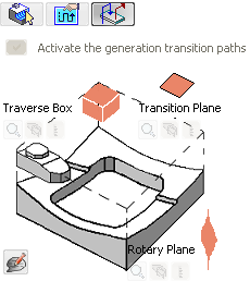
Activate the Generation of Transition Paths
Except for a mill-turn or a lathe machine, you can activate the generation of
transition paths from the Transition Path tab.
-
Select Transition Path
 . .
-
Select the Activate the generation Transition Paths
check box.
The icons used to specify the required geometry become available.
Note:
When the check box Generate Transition Path is:
- Selected: The Manufacturing Program
context menu items Generate Machine Rotations and
Delete Generated Machine Rotations
are not available. All the generated machine rotations are removed
from the Activities Process Tree.
- Cleared: The Manufacturing Program
context menu items Generate Machine Rotations and
Delete Generated Machine Rotations
are available.
- See Inserting Machine Rotations.
-
Click Traverse Box
Plane, then select five planes that define a global traverse
box for the Part Operation.
-
Click
Transition Plane, then select the planes that are
used as a global transition planes for the Part Operation.
-
Click Rotary
Plane, then select the planes that is used as a global
rotary plane for the Part Operation.
Select the Milling Head Mount Point from a List
When you select a head, the available mount points are listed, then you can
select one of those mounting points for the Part Operation.
-
In the Activities Process Tree, right-click a Head Change operation.
-
Select the required head from the list of available mount points, such as
Mount_Point_1.
Note:
The machine simulation uses the selected head mount point and also
checks reachability.
See also Inserting Head Changes.
|

