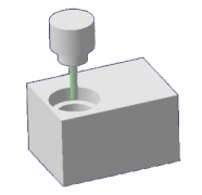
Tool Path Simulation
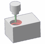
Simulating a tool path allows you to verify its validity. A combination of tools and options allows you to simulate and verify the computed tool path. The tools that appear when you click Play in the Compass are described below.
Experience Player
The experience player allows you to control the tool path simulation. For more
information, see Players.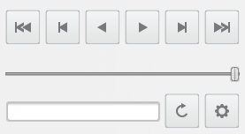
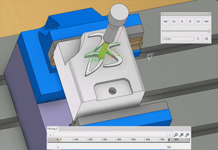
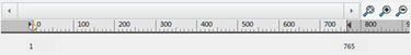
Tool Path Line
The tool path line provides information on the tool path, such as collisions and kinematic issues. It allows you to simulate a section of the tool path to analyze it in more detail. You can also use the tool path line to jump to the end of the simulation by sliding the current point to the end.
By default, the tool path line is hidden: you can display it by clicking the
arrow  at the bottom of the work area.
The tool path line includes the following elements:
 |
|
 |
|
 |
|
 |
|
 |
|
 |
|
|
|
|
Simulation Options
The simulation options appear next to the tool path line and allow you to display the tool path, tool position, and tool trajectory in different modes. It also allows you to display information about the machine. The options also allow you to take the TRACUT into account during simulation.
 |
|
 |
|
 |
|
 |
|
 |
|
|
|
 |
|
| Tool Position | |
 |
|
 |
|
 |
|
| Trajectory | |
 |
|
 |
|
 |
|
 |
|
| TRACUT | |
 |
|
 |
|
| Display | |
 |
|
 |
|
| Material Chunks | |
 |
|
 |
|
Partial Tool Path Simulation Behavior
A partial tool path simulation is defined by the start and end points you position on the tool path line, using the displayed arrows.
You can simulate either a machining operation or a manufacturing program. When simulating a manufacturing program, the start, current, and end points displayed on the tool path line correspond to the machining operation tool path positions.
- You cannot simulate a partial tool path:
- For multiple or auxiliary operations such as tool change, transition path, COPY operator, and machine rotation.
- In Plane by Plane
 and Feedrate by Feedrate
 modes. If you switch to one of these modes, the positions
are restored to full tool path and the editor boxes are
unavailable. The behavior of these simulation modes is then
the same as for the complete tool path.
modes. If you switch to one of these modes, the positions
are restored to full tool path and the editor boxes are
unavailable. The behavior of these simulation modes is then
the same as for the complete tool path.
- For Profile Contouring operations created with the cutter profile output option, both the cutter profile and tip trajectory are displayed in the simulation.
Collision and Kinematic Issues Checking
Points and areas in collision are displayed both in the tool path line and work area once you select the Activate Collisions Checking check box in the Options tab of the Part operation dialog box. You can also verify kinematic issues, such as out-of-limit points, by selecting the Activate Kinematics Checking check box in the Part operation dialog box. For more information, see Creating a Part Operation.
Display of Collision and Kinematic Issues in the Tool Path Line
Collision and kinematic issues detected in the tool path computation are identified by colored areas on the tool path line. The graduation of the tool path line identifies precisely where in the tool path the collision or kinematic issues occur.
 > Preferences > App Preferences > Simulation > Machining
.
> Preferences > App Preferences > Simulation > Machining
. A red area identifies a collision. On the picture below, the collision is
located between point 50 and point 110 of the tool path. 
On the picture below, the blue area identifies the out-of-limit points and
the yellow stripe identifies an angular variation.
Collision Display on the work area

When you move the pointer onto a collision point, the maximum collision depth and the intersection between the tool and the part are displayed.
Collisions checks are done at each point and between points of the tool path:
- If the tool is in collision at a point of the tool path, a red cross is displayed at that point.
- If the tool is in collision on at least a part of a segment of the tool path, the whole segment is displayed in red. In this case, a red cross is displayed at the end point. In this case, the intersection between the tool and part is not displayed.
For the update mechanism:
- If a user representation is modified during a session, the
modification is not recognized and collision checking is not
automatically recomputed. Force the computation of the operation by
selecting Forced Computation when you click
Compute Tool Path
 from the Activities Process Tree. You can also click Compute Tool Path and
Simulate
from the Activities Process Tree. You can also click Compute Tool Path and
Simulate
 to start the simulation after computing the path.
 - When collision checking is active and you modify the user representation of a tool of an operation whose tool path is simulated, collision checking is not recomputed.
Transition Paths Between Operations
A transition path from machining operation A to machining operation B is represented by a dashed line. Its color depends on the feedrate. This feedrate depends on whether a clearance macro is present:
- If a clearance macro is activated on machining operation B, the feedrate of the clearance path is used for the transition path.
- If no clearance macro is activated on machining operation B, the
feedrate depends on whether the Set Rapid feedrate at start
of operations check box in the Generate NC
Output Interactively dialog box is selected:
- If the check box is selected, a RAPID feedrate (red) is used for the transition path.
- If the check box is not selected, the first feedrate defined on machining operation B is used for the transition path (for example, yellow for approach or green for machining). See Generate the NC Code Interactively.
Color Coding After APT Import
When simulating the tool path of a machining operation after importing a file in APT format, the feedrate colors are not respected. This is because no information is provided about the tool path type (approach, machining, retract, and so on) in the APT file. In this case:
- The machining feedrate color is assigned to the tool path with the smallest feedrate value.
- The approach feedrate color is assigned to the tool path with the next higher feedrate value.
- The retract feedrate color is assigned to the tool path with the next higher feedrate.
Influence of the Hide/Show Status of Selected Elements
The material removal simulation takes into account only the visible subelements of bodies selected as stock, design, or fixture. The following rules summarize the tool path computation behavior depending on the Hide/Show status of the selected element.
- Bodies used as part, check, or fixtures are taken into account in the tool path computation, whether they are visible or not.
- Subelements (for example, faces) of a Body, used as part, check, or fixture, are taken
into account in the tool path computation only if they are
visible.Note: If the hide/show status of Sub-elements is changed, the machining operations using this geometry must be force recomputed manually.
- Set of faces used as part, check or fixture are taken into account in the tool path computation regardless of whether they are visible or not.
Influence of the Faces Selection Mode
By boundary of faces allows you to select a surface from the tree while By belt of faces allows only the selection from the work area, because:
- In all cases, the tool path computation supports only a contour of edges, which is retrieved from the selected faces.
- This contour is not created in the same way with By belt of faces or By boundary of faces.
- By boundary of faces
- The edge contour is the external boundary of selected faces. However, all faces must be topologically convex, which is where they share adjacent edges. The edges used by the tool path computation algorithm exist in the design.
- By belt of faces
- This situation is more complex because:
- The contour must be a belt of faces: each face must be near only one other face of the belt, except if the contour is closed.
- The faces must be ruled along the same axis (tool axis).
- The faces must be topologically adjacent.
- The order of the faces contributes to the stability of the material side in the case where the belt of face is not closed (for Profile Contouring).
The edges used by the tool path computation do not exist in the design. To get the contour of edges and the boundary of faces, it is projected onto the bottom plane of the bounding box of the belt, and wireframe elements with free vertices are deleted.
When you select an object in the tree, you do not select the faces but the complete feature whose result can include more than one face. Those faces are not required built as a belt of faces. Moreover, the number and position of the faces included in the feature is user-defined. In this case, it may not be possible to compute the machining operation.

 from the
  in the