Creating a Groove Turning Operation | ||||
|
| |||
-
From the
Turning Machining section of the action bar, click Groove Turning
 .
The operation is added to the manufacturing program.
.
The operation is added to the manufacturing program.The Groove Turning dialog box opens on the Geometry tab
 .Note: The Geometry tab includes a sensitive area to help you specify the geometry to be machined. The part and rough stock are colored red indicating that this geometry is required. All other geometry is optional.
-
Still in the Geometry
tab
 .
.
-
Click the red part area in the Geometry tab and then select the desired part profile in the work area.
See Selecting Edges and Faces to Define Geometry
Once selected, the part area changes color to green indicating that this Geometry is defined.
-
Click the red rough stock area in the Geometry tab and then select the desired rough stock profile in the work area.
Once selected, the rough stock area changes color to green indicating that this Geometry is now defined.
-
Click the red part area in the Geometry tab and then select the desired part profile in the work area.
-
Select the Strategy
tab
 .
.
-
Specify the machining strategy parameters.
- Orientation: External
- First plunge position: Center
- Next plunges position: To head rough stock
-
Double-click Max depth of cut.
Set this value to 2.5mm in the Edit Parameter dialog box and click OK.
- Set other optional parameters in the Option and Corner Processing tabs.
-
Specify the machining strategy parameters.
-
Go to the Tool
tab
 to select a
tool.
For more information, see Tool Parameters and Assigning a Tool Element to a Machining Operation.
-
Select the Feeds and Speeds
tab
 to specify the
feedrates and spindle speeds for
the machining operation.
-
In the Macros
tab
 , add approach and retract motions to
the machining operation.
Approach linking and retract linking motions are interruptible for this type of machining operation.
, add approach and retract motions to
the machining operation.
Approach linking and retract linking motions are interruptible for this type of machining operation.For more information, see Defining Macros on Turning Operations.
-
Click Simulate or Display to check the validity of the machining operation.
For more information, see Simulating the Tool Path.
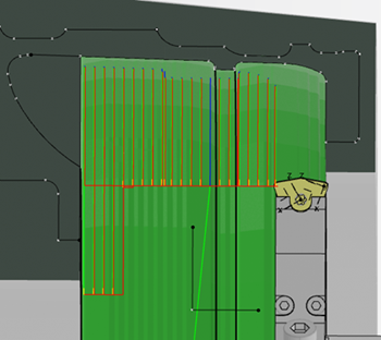
The tool path is computed. For grooving turning operations, an extra pass that follows the groove flank is generated. The extra pass removes material on flanks parallel to the previous machining pass only.
- Click OK to create the machining operation.