Creating a Sequential Turning Operation | ||
| ||
-
From the Turning Machining section of the action bar,
click Sequential Turning
 .
A sequential turning item is added to the manufacturing program.
.
A sequential turning item is added to the manufacturing program. -
In the Sequential Turning Operation dialog box that
appears, create the following motions in the Strategy tab:
-
Select Go
 and
define the first motion parameters.
and
define the first motion parameters.
The first motion must be a Go motion.
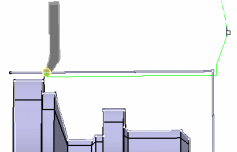
- In the dialog box that appears, click one of the red lines and select a check element in the work area.
- Click OK to define the motion.
-
Select Go
again and
define the second motion parameters.
- In the dialog box that appears, click one of the red lines and select a check element in the work area.
- Right-click First check mode and Second check mode and select To.
- Set the Offset on check value of the First check element to 2mm.
- Click OK to define the motion.
-
Optional: Select Go
again and
define the motion parameters.
- In the dialog box that appears, click one of the red lines and select a check element in the work area.
- Right-click First check mode and Second check mode and select Past.
- Set the Offset on check value of the Second check mode to 5mm
- Click OK to define the motion.
-
Select Go InDirv
 .
.
- Select the drive direction (red line) and select a linear element in the work area.
- Select a check geometry in the Geometry tab then select the desired check element in the work area.
- Set the Check Mode to To and the Offset on check: 5mm.
- Click OK to define the motion.
-
Select Follow
 .
The check curve of the previous motion is used as drive curve. This drive element is highlighted in the work area.
.
The check curve of the previous motion is used as drive curve. This drive element is highlighted in the work area. - Select a check geometry in the Geometry tab and then select the desired check element in the work area.
- Set the Check Mode to To.
- Click OK to define the motion.
-
Select GoTo Point
 .
.
- Select a check geometry in the Geometry tab and select the desired check element in the work area.
- Specify values in the Axial offset and Radial offset text boxes.
- Click OK to define the motion.
You can define the tool axis for each motion using the
 icon that
appears in the viewer.
icon that
appears in the viewer. -
Select Go
-
Go to the Tool tab
 to select a
tool.
to select a
tool.
-
Select the Feeds and Speeds tab
 to specify the
feedrates and spindle speeds for the Machining Operation.
to specify the
feedrates and spindle speeds for the Machining Operation.
-
Select the Macros tab
 to specify the
operation's transition paths.
For more information, see Defining Macros on Turning Operations.
to specify the
operation's transition paths.
For more information, see Defining Macros on Turning Operations. -
Click Simulate or Display to check the validity of the Machining Operation.
- The tool path is computed.
- A progress indicator is displayed.
- You can cancel the tool path computation at any moment before 100% completion.