Define Geometrical Links for Each Operation
After the creation of all data, a sizable panel is displayed. It contains a view of each geometrical link to reconnect for all elements of machining programming: Machining Feature, and Machining Operation.
Commands
In the viewer, the following commands let you manage the definition of geometrical links:

|
Lets you define the operation as complete. |

|
Lets you define the operation as incomplete. |

|
Lets you enter a comment. |
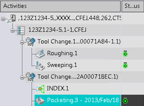
Viewing a Machining Operation
In this dialog box, you can display all the geometrical links of operation.
You display and edit the following geometrical links:
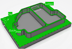
- Position: Lists the setup position defined in the part operation and displays the NC Assembly setup in the 3D area.
- Feature: Geometric feature exported (such as Surface Feature, Simple Pattern, Geometric Area Exported or Offset Group).
- Strategy: Geometric link to strategy definition.
- Geometry: Adds specific geometry.
- Macro: Geometric link to macro definition.
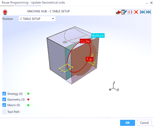
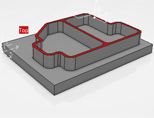
The link is highlighted in green if it is correctly defined, or in red if it has to be redefined. You can define links by selecting the label in the viewer.
To simplify the view, define what you want to see by selecting of one or several of the options (Feature, Strategy, Geometry, orMacro).
By default, all the Feature, Strategy, Geometry, and Macro links are displayed.
You have an additional option to display the Tool Path of
an initial Machining Operation (from the Process Machining
selected at the beginning of the operation). 
 icon in
the
icon in
the 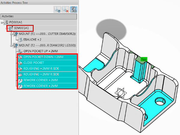
 :
Define the NC Assembly setup target (mandatory if displayed).
:
Define the NC Assembly setup target (mandatory if displayed).  : Define the mount point.