-
From the Analysis &
Output section of the action bar, click Design Part Comparison
 .
.
-
In the Design Part Comparison dialog box that appears,
specify the Tolerance. The value is defined as 0.1mm by
default.
-
Specify the Offset. For more information, see Offset.
- Optional:
Select Ignore Uncut Areas to ignore uncut areas of the
current rough stock during comparison.
-
Select the Accuracy: Low,
Medium, or High.
-
Select
the Automatic Refresh check box to maintain the high
quality of the image after a view change.
-
Select the Transparency check box to only display gouges
or the remaining part to detect issues at the first sight of problems. Use the
slider to manage the level of transparency from 0 (no transparency) to 255 (full
transparency).
-
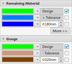
Specify the tolerance bands in the Remaining Material and
Gouge areas.

-
Click Apply.
The machined stock is compared with the design part, based
on the specified options.

Notes:
- Any point on the machined stock is considered a fault if the distance (deviation) to the
design part surface is greater than the specified tolerance.
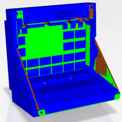
- The results of the comparison are reflected on the workpiece, based on the
severity of the fault and the configured color settings.

