Assign a Mill-Turn Machine and Create the Setups
You need to assign a mill-turn machine and to create setups in the Part Operation.
-
Define and order the setups in the Part Operation as explained in Creating a Part Operation.
For example:
In a scenario where the stock is first machined on the main spindle (Setup.1), split into 2 at an intermediate position (Setup.2) and then further machined on the counter spindle (Setup.3), the mounting of the setups should be as follows:
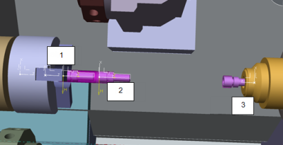
1- Setup.1: The part is mounted on the main spindle and is in activated state.
2- Setup.2: The part is mounted on the main spindle and is in deactivated state.
3- Setup.3: The part is mounted on the counter spindle and is in deactivated state.
The stock is first machined at SetUp.1 position after which the counter spindle grabs the stock and moves it to Setup.2 position where the stock is split into two. The counter spindle returns to its home position (Setup.3) along with the split stock for further machining.
During material removal simulation, the actual number of stocks involved in the scenario is decided by the number of mounted setups that are in activated state. For example in the above scenario Setup.1 should be mounted and in activated state. Setup.2 and Setup.3 may be mounted (to enable defining of machining operations at these setup locations, but it should be in deactivated state.
 and the


