Using User Defined Functions | ||||||
|
| |||||
-
Click to create a
New Machining Process
 in the
Machining Process view.
in the
Machining Process view.
-
Define a set of Machining Operations.
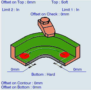
We will use Profile Contouring in this scenario.

-
Click
Profile Contouring
 from the
Prismatic Machining section.
See Creating Profile Contouring Operations
from the
Prismatic Machining section.
See Creating Profile Contouring Operations -
Click
 to search
From Session for the
Part.
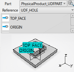
The Physical Product appears in the object selection dialog box. The related UDF features are available in Reference pull-down window.
to search
From Session for the
Part.
The Physical Product appears in the object selection dialog box. The related UDF features are available in Reference pull-down window.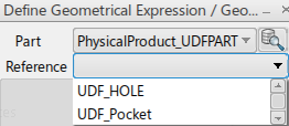
The exposed or linked parameters appear. -
Select the relevant parameters (UDF_Pocket)
and associate the geometric features in the
Profile Contouring dialog box image.
-
Type
10mm and use the
Arrow up to add it to the List of
query constraints.

-
Click
Drilling
 from
Axial Machining section to create another
machining operation.
from
Axial Machining section to create another
machining operation.
-
Click
UDF_HOLE from
Reference.