Creating a Multi-Axis Helix Machining Operation in Interpolation Mode | |||||
|
| ||||
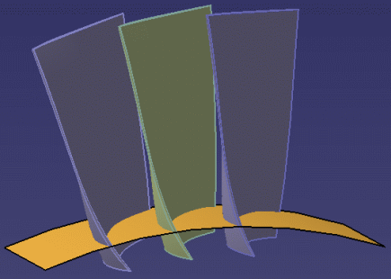
- The following procedure describes how to machine the middle
(green) blade of the part shown below with no tool collisions with the two
neighboring blades.
- From the Surface Machining section of the action bar, click Multi-Axis Helix Machining
 .
.
A Helix Machining entity is added to the manufacturing program. The Multi-Axis Helix Machining dialog box opens directly at the Geometry tab
 .
.The part surface, upper and lower contours, and leading and trailing edges of the sensitive icon are colored red indicating that this geometry is required and must be selected.
The upper and lower contours and the leading and trailing edges must lie on the faces selected as part surface. Selection of check elements (such as neighboring blades or fixtures) is optional.
- Still in the Geometry tab, select the leading and trailing edges to define the limits
of the machining.
The Edge Wizard appears to help you select these contours.
Note: They must intersect the upper and lower contours.- 1 = upper contour
- 2 = lower contour
- 3 = trailing edge
- 4 = leading edge
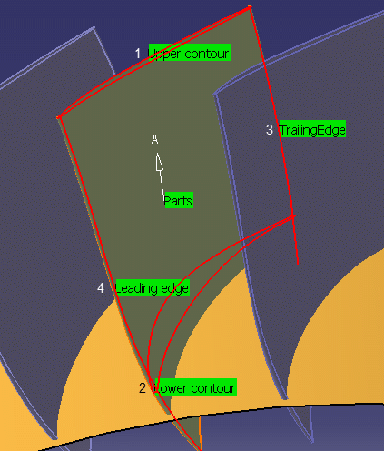
- The geometry entities of the icon are now colored green indicating that this geometry is now defined.
- At this stage, make sure the Collision Checking option in the Geometry tab is deactivated.
- Go to the Tools tab
 to select a tool, for example a conical mill tool
with the following characteristics.
to select a tool, for example a conical mill tool
with the following characteristics. - Go to the Strategy tab
 :
:- Set the Tool Axis Mode to Interpolation.
- Select a Start point by first clicking a point symbol in the sensitive icon then selecting any point on the part surface.
- Click one of the interpolation
axis symbols in the sensitive icon.
Default Interpolation axes (I.1 to I.4) are displayed at the four corners of the part.

The Interpolation Axes dialog box is displayed.
All the interpolation vectors are listed with their position, direction and status.
- In the Interpolation Axes dialog box:
-
Pick a vector in the dialog box.It is highlighted in the work area.
-
Click
 to add an interpolation vector.
The Interpolation Axes dialog box disappears.
-
Pick in the work area to indicate the position of this new
interpolation vector.Its Axis Definition dialog box appears (see below).
- Click OK in the dialog boxes when you are done.
- Click
 to
remove the interpolation vector selected in the dialog box.
to
remove the interpolation vector selected in the dialog box. - Click
 to edit
the interpolation vector selected in the dialog box. The Axis Definition dialog box is displayed.
to edit
the interpolation vector selected in the dialog box. The Axis Definition dialog box is displayed. - Click OK in the dialog boxes when the interpolation axes are defined.
-
Pick a vector in the dialog box.
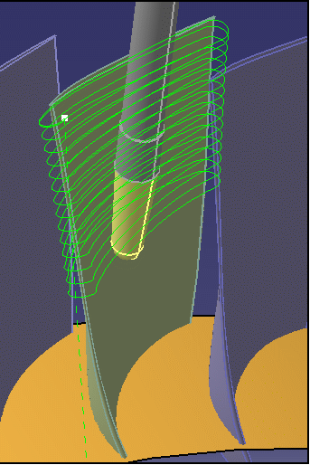
- If necessary, adjust the interpolation axes and possibly
insert additional interpolation axes until the tool path is collision free.
The following figure shows an example of the default and additional interpolation axes that will give a collision-free trajectory.
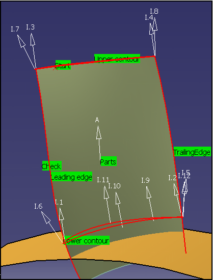
The corresponding data is as follows:
Axis
Application point coordinates
Interpolation axis vectors
1
Intersection point
u=0.224917 v=0.0174524 w=0.974222
2
Intersection point
u=0.292194 v=-0.0348995 w=0.955722
3
Intersection point
u=0.15643 v=0 w=0.987688
4
Intersection point
u=0.308264 v=0.0697565 w=0.94874
5
x=-20.8009 y=18.814 z=192.1
u=-0.0688977 v=0.156434 w=0.985282
6
x=23.0488 y=-11.0264 z=192.676
u=0.103351 v=-0.529919 w=0.841727
7
x=12.9556 y=-22.0174 z=252
u=0 v=-0.45399 w=0.891007
8
x=-10.2918 y=16.9498 z=252
u=-0.069714 v=0.0348995 w=0.996956
9
x=-14.1239 y=9.91563 z=192.142
u=0.25878 v=-0.0174524 w=0.965779
10
x=-4.66894 y=1.32628 z=191.888
u=0.207785 v=-0.0348995 w=0.977552
11
x=-5.69227 y=-3.93598 z=192.877
u=0.0347667 v=-0.0871557 w=0.995588
12
x=-20.6779 y=19.1817 z=191.995
u=0.137059 v=0.173648 w=0.975224
-
Click Display or
Simulate to check for collisions.