About Drilling and Riveting Processes | ||||
|
| |||
An automated Drill and Rivet machine is composed of head and an anvil. At each rivet origin, a specific sequence needs to be simulated.
The main inputs of the operation are:
- A manufacturing pattern owning a sequence of manufacturing fasteners.
- Several instruction sets describing the sequence of motions to be simulated before and after each rivet origin.
- Macro motions describing the Cartesian motions of the machine head between the rivet origins.
A typical Drilling Riveting operation allows the following:
- Move the machine head following approach
macro motion
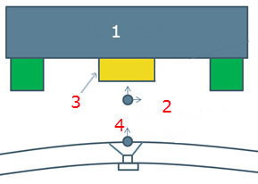
1 - Machine head
2 - Machine head TCP
3- Pressure foot
4- Rivet origin
- Apply approach instruction set (typically to move the anvil at working position)
- Move the machine head up to the first rivet origin (defined by manufacturing fastener)
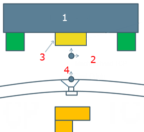
- Apply fastening instruction set (typically to move the anvil and the pressure foot)
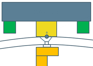
- Move the machine head to the position of next manufacturing fastener (following linking and clearance macro motions). Apply the approach and fastening instruction sets.
- Retract the machine head following retract macro motion.
Right-clicking on a fastener point gives access to contextual commands. See Context Menus.